
The basics of trip curves for panel builders
A critical but often confusing characteristic of miniature circuit breakers are trip curves. Knowing the basics of trip curves can ensure selecting the lowest-cost breaker that will provide the needed protection without nuisance tripping.
To the average consumer, circuit breakers are basic on/off devices that trip when they detect incoming current above the rated threshold. Panel builders, however, understand that breakers operate in a far more sophisticated way considering multiple variables: variables that can be represented graphically in a trip curve that shows the range of conditions that will initiate a trip.
Selecting the optimum miniature circuit breaker (MCB) is critical to helping ensure proper protection, with minimal or no nuisance tripping, at the lowest possible cost. Matching a breaker to an application requires an understanding of the basics of trip curves.
Molded-case versus miniature circuit breakers
Almost every electrical-protection device operates based on a simple formula: If THIS, then THAT. Some large, molded-case circuit breakers can be adjusted to adapt the breaker to the application, reacting to THIS variable with the appropriate THAT response.
This adjustability enables panel builders to select a molded-case breaker with the required specifications – plus a “safety factor” to account for application unknowns or future equipment changes – and then “tune” the breaker once it’s in use.
MCBs, on the other hand, operate based on only two parameters that cannot be adjusted: overload and short-circuit. Even with just these two basic parameters, though, breaker buyers have a broad selection of MCBs that could potentially meet their application requirements. Selecting the appropriate breaker includes considering not just features like amperage, voltage, and interrupting rating, but also trip curves.
Trip curve basics
Most protective devices have a defined trip curve, also referred to as a time/current curve, that describes their behavior. The curve is represented in a graph showing how the breaker will respond to changes in current, basically the high- and low-current thresholds, that will cause a trip.
The optimum trip curve balances overcurrent protection and machine operation. A fast-acting trip curve will do an excellent job of protection, but at the cost of frequent and costly nuisance tripping (mostly due to inrush currents of motors and transformers). A breaker with higher trip points will better keep the process up and running.
Trip curves are defined by IEC standards 60898-1 and 60947-2. The curves represent two different trip functions: thermal and electromagnetic. The thermal section (top/red area of the chart) that responds to overloads typically consists of a bi-metallic strip. The thermal trip unit responds relatively slowly and is consistent across all trip curves.
The short-circuit section (bottom/grey) relies on a magnetic coil or solenoid that opens when the overcurrent’s design limit is reached. This section of the breaker responds within milliseconds. This characteristic of the trip curve has no counterpart on the UL side.
The concept of trip curves originated in the IEC world, and the alphabetic code used to categorize MCBs carried over from IEC standards. They define the lower and upper thresholds for tripping (no-trip threshold and trip threshold). The trip-curve graph shows the tolerance band within which manufacturers can set the individual tripping point of their breakers.
The characteristics of the magnetic/short-circuit trip unit and applications of each curve, from most- to least-sensitive are: Z: Trips at 2 to 3 times rated current. Suitable for highly sensitive applications, e.g., semiconductor devices. B: Trips at 3 to 5 times rated current. C: Trips at 5 to 10 times rated current. Suitable for medium inrush currents. K: Trips at 10 to 14 times rated current. Suitable for loads with high inrush currents, mostly for use with motors and transformers. D: Trips at 10 to 20 times rated current. Suitable for high starting currents.
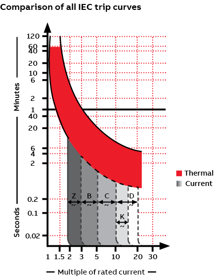
Referring to the graph above, you can see that higher currents trigger more rapid trips.
The ability to tolerate inrush current is an important consideration in trip-curve selection. Certain loads, notably motors and transformers, experience a momentary change in current – the inrush current – at contact closure. Faster protective devices, like a B-trip curve, would see this inrush as a fault and open the circuit. For these types of loads, trip curves with a higher magnetic tripping point, either D or K, can “ride through” the momentary inrush of current, protecting the circuit without nuisance tripping.
Choosing the right trip curve
Experienced panel builders can often identify the appropriate trip curve for various applications but may require some trial and error to arrive at the optimum breaker. For many panel builders, though, the best approach may be to consult with your device manufacturer or distributor. Provide them with the details of your application, and they should be able to recommend the right miniature circuit breakers to meet your needs.
See related blog post “Choose enhanced breaker and controller options to build more-competitive panels” .
Thomas Weinmann
Senior Product Marketing Manager
ABB Electrification Business
Presented by:
This site is created by ABB application engineers and experts as an educational tool to help engineers.

- Get custom product tools and services
- Access training
- Manage support cases
- Create and manage your orders (authorized partners only)
Schneider Electric USA Website
Search FAQs
What is a qo, qob, or qou high magnetic breaker (suffix hm), and is it marked anywhere on the breaker.
Released for: Schneider Electric USA
Articles that might be helpful
Discuss this topic with experts
Start here!
Find answers now. Search for a solution on your own, or connect with one of our experts.
Contact Support
Reach out to our customer care team to receive more information, technical support, assistance with complaints and more.
Where to buy?
Easily find the nearest Schneider Electric distributor in your location.
Search topic-related frequently asked questions to find answers you need.
Contact Sales
Start your sales inquiry online and an expert will connect with you.
TM-D Thermal-Magnetic Trip Unit for 1P and 2P Circuit Breakers
Introduction
The TM-D thermal-magnetic trip unit for 1P/2P circuit breakers up to 160 A are built-in trip units.
They are designed for AC and DC general-purpose applications.
The TM-D built-in 1P/2P trip units provide:
o fixed thermal threshold
o fixed magnetic pickup
Setting the Thermal Protection
The thermal protection pickup Ir cannot be adjusted and equals the value shown below:
Setting the Magnetic Protection
The magnetic protection pickup cannot be adjusted and equals the value shown below:
DOCA0140EN-01
© 2020 Schneider Electric. All rights reserved.
Selectivity techniques
The different selectivity techniques, also from the operational point of view.
Selectivity (discrimination) is achieved by automatic protective devices when a fault is cleared by the protection device installed immediately upstream of it, while all the other protection devices remain unaffected.
Two areas can be defined, depending on the current ranges and circuit-breaker trip curves:

In which the thermal protection for thermal-magnetic trip units and protection L for electronic trip units are normally called upon to trip.

In which the magnetic protection for thermal-magnetic trip units or protections S, D and I for solid-state trip units are normally called upon to trip.
Time-current selectivity
Current selectivity, time selectivity, energy selectivity, zone selectivity.
The protections against overload generally have a definite time characteristic, whether they are realized by means of a thermal trip unit or by means of function L of an electronic trip unit. By definite time characteristic we mean a trip characteristic for which, as the current increases, the trip time of the circuit-breaker decreases.
When there are protections with this type of characteristics, the selectivity technique used is time-current selectivity. Time-current selectivity realizes trip selectivity by adjusting the protections so that the load-side protection, for any possible overcurrent value, trips more rapidly than the supply-side circuit-breaker.
When the trip times of the two circuit-breakers are analyzed, it is necessary to consider:
- The tolerances over the thresholds and trip times;
- The real currents circulating in the circuit-breakers.
With regard to tolerances, ABB SACE makes the trip curves of its trip units available in the technical catalogues and in DOCWin software. In particular, in the curve module of DOCWin, the curves of both the electronic and thermomagnetic trip units include the tolerance values. Thus, a trip of the protection unit is represented by two curves, one showing the highest trip times (top curve), and the other one indicating the most rapid trip times (bottom curve).
- the supply-side circuit-breaker trips according to its own bottom curve.
- the load-side circuit-breaker trips according to its own top curve.
- if the two circuit-breakers are passed through by the same current, it is sufficient that there is no overlapping between the curve of the supply-side circuit-breaker and of the load-side circuit-breaker;
- if the two circuit-breakers are passed through by different currents, it is necessary to select a series of significant points on the time current curves and check that the trip times of the supply-side protection are always above the corresponding times of the load side protection.
- 1.05 x I1 1 of the supply-side circuit-breaker (value below which the supply-side protection never trips)
- 1.20XI3 (or I2) 2 of the load-side circuit-breaker (value above which the load-side protection certainly trips with the protections against short-circuit).

- 1.05 is the value for minimum definite non-intervention defined in the Standard (IEC60947-2). For some types of circuit-breakers this value could vary (see the technical catalogue for further information).
- 1.2 is the value for maximum definite intervention for protection against short-circuit defined in the Standard (IEC60947-2). For some types of circuit-breakers, this value might be lower (see the technical catalogue for further information).
This type of selectivity is based on the observation that the closer the fault point to the power supply source of the installation, the higher the short-circuit current. Therefore, it is possible to discriminate the zone where the fault occurs, by setting the instantaneous protections to different current values.
Total selectivity can normally be achieved in specific cases only where the fault current is not high and where there is a component with high impedance interposed between the two protections (transformer, very long cable or a cable with reduced cross-section, etc.), and consequently there is a great difference between the short-circuit current values.
Therefore, this type of coordination is used above all in final distribution (low rated current and short-circuit current values, and high impedance of the connection cables). The time-current trip curves of the devices are normally used for this study. It is intrinsically fast (instantaneous), easy to realize and cost-effective.
- The ultimate selectivity current is usually low and therefore selectivity is often partial;
- The setting level of the protections against overcurrent rises rapidly;
- It is impossible to have redundancy of protections, which guarantees that the fault is cleared rapidly if one protection fails to operate.
This type of selectivity can also be realized between circuit-breakers of the same size not providing time-delayed overcurrent protection (S).
- The protection against short-circuit of the supply-side circuit-breaker A shall be set to such a value that it does not trip for faults occurring on the load side of protection B. (In the example in the figure I3 minA > 1kA)
- The protection of the load-side circuit-breaker B shall be set to such a value that it trips for faults occurring on its load side. (In the example in the figure I3 MaxB < 1kA)
Obviously, the setting of the protections must take into account the real currents circulating in the circuit-breakers.

This selectivity limit, associated to the magnetic threshold of the supply-side circuit-breaker, is exceeded in all cases where energy type selectivity is realized. If the settings indicated for energy selectivity are respected, for the combinations of circuit-breakers with an energy selectivity value given in the coordination tables published by ABB, the selectivity limit to be taken into consideration is the one given in the tables and not the one obtained by using the above mentioned formula.
The ultimate selectivity value that can be obtained is equal to the instantaneous trip threshold of the supply-side protection minus any tolerance value. Is = I3 minA

This type of selectivity is a development of the previous one. For this type of coordination, in addition to the current trip threshold, a trip time is also defined: a certain current value will make the protections trip after a defined time delay, such as to allow any protection placed closer to the fault to trip, excluding the area of the fault. Thus, the setting strategy is to increase gradually the current thresholds and the trip delays by getting closer to the power supply sources (setting level directly correlated to the hierarchical level). The delayed trip thresholds must take into account the tolerances of the two protection devices and the effective currents flowing through them.
The difference between the delays set for the protections in series must take into account the times of fault detection and clearance of the device on the load side and of the inertia time (over-shoot) of the device on the supply side (time interval during which the protection can trip even when the phenomenon is over). As in the case of current selectivity, the study is made by comparing the time-current trip curves of the protection devices.
Speaking generally, this type of coordination:
- is easy to study and realize;
- is not very costly as regards the protection system;
- allows even high selectivity limit values to be obtained (if Icw is high);
- permits redundancy of the protection functions.
- the trip times and energy levels let through by the protections, especially by those close to the sources, are high.
This type of selectivity can also be realized between circuit-breakers of the same size, equipped with electronic trip units providing time-delayed overcurrent protection.
The protections against short-circuit of the two circuit-breakers will be set:
- With the I 2 trip thresholds against time-delayed short-circuit set so as not to create trip overlapping, taking into consideration the tolerances and the real currents circulating inside the circuit-breakers;
- With t 2 trip times set so that the load-side circuit-breaker B clears the fault, whereas the supply-side circuit-breaker A , still in its timing phase, manages to "see" the extinction of the current and thus remains closed.

The ultimate selectivity limit obtained is equal:
- To the instantaneous trip threshold of the supply-side protection, if this function is enabled, minus the tolerance (if any): Is = I3 minA
- To the Icw value for supply-side air circuit-breakers when the instantaneous protection function is set to OFF.

Note These selectivity limits are exceeded in all the cases where energy type selectivity is realized. If the settings indicated for energy selectivity are respected for the combinations of circuit-breakers with an energy selectivity value given in the coordination tables published by ABB, the selectivity limit to be taken into consideration is the one given in the tables, and not the one that can be obtained from the considerations in this paragraph.
The coordination of the energy type is a particular type of selectivity that exploits the current-limiting characteristics of moulded-case circuit-breakers. It is recalled that a current-limiting circuit-breaker is "a circuit-breaker with a break-time short enough to prevent the short-circuit current reaching its otherwise attainable peak value" (IEC 60947-2). In fact, all the ABB SACE moulded-case circuit-breakers of the Tmax series, the miniature circuit-breakers and the air current-limiting circuit-breaker E2L and E3L have more or less marked current-limiting characteristics. Under short-circuit conditions, these circuit-breakers are extremely fast (trip times in the range of a few milliseconds) and open when there is a strong asymmetrical component. Thus, it is impossible to use the time-current trip curves of the circuit-breakers, obtained with symmetrical sinusoidal types of wave forms, for the coordination study.
These phenomena are mainly dynamic (therefore proportional to the square of the instantaneous current value) and are heavily dependent on the interaction between the two devices in series. Therefore, the end user cannot determine the energy selectivity values. The manufacturers provide tables, slide-rules and calculation programs giving the ultimate current selectivity values of I s under short-circuit conditions for different combinations of circuit-breakers. These values are defined by theoretically integrating the results of tests carried out in compliance with the prescriptions in Annex A of Std. IEC 60947-2.
The short-circuit protections of the two circuit-breakers shall observe the conditions below.
- Supply-side thermomagnetic trip unit
- Supply-side electronic trip unit

The ultimate selectivity limit Is obtained is the one given in the tables ABB SACE makes available for its customers.
This type of coordination is an evolution of time coordination. In general, zone selectivity is realized by means of dialogue between the current measuring devices that, once the setting threshold has been detected as having been exceeded, allows the fault zone to be identified correctly and the power supply to the fault to be cut off.
It can be realized in two ways:
- The measuring devices send the information on the current setting threshold having been exceeded to a supervision system and the latter identifies which protection has to intervene;
- When there are current values exceeding their setting, each protection sends a lock signal by means of a direct connection or a bus to the hierarchically higher level protection (on the supply side in relation to the power flow direction) and, before intervening, checks that a similar lock signal has not arrived from the load-side protection. Thus, only the protection immediately on the supply side of the fault trips.
This second way guarantees without doubt shorter trip times. Compared with a coordination of the time type, the need to increase the intentional delay as one moves towards the power supply source is no longer necessary. The delay can be decreased to the time needed to exclude the presence of a possible lock signal coming from the load-side protection. This type of selectivity is suitable for radial networks and, when associated with directional protection, is suitable for meshed networks too.
Compared with the coordination of time type, zone selectivity permits:
- a reduction in the trip times (these can be lower than hundred milliseconds);
- a reduction both in the damage caused by the fault and in the interferences in the power supply system;
- a reduction in the thermal and dynamic stresses on the components of the installation;
- a very high number of selectivity levels.
- it is more burdensome both in terms of cost and of complexity of the installation;
- it requires an auxiliary supply.
As a result, this solution is mainly used in systems with high rated current and short-circuit current values and with binding requirements for safety and service continuity. In particular, examples of logical selectivity are often found in the primary distribution switchgear placed closely on the load side of transformers and generators.
This type of selectivity can be realized:
- between Emax 2 air circuit-breakers equipped with Ekip Touch and Ekip Hi-Touch trip units. The ultimate selectivity limit which can be obtained is equal to the Icw Is = Icw
- between Tmax T4L,T5L and T6L moulded-case circuit-breakers equipped with PR223 EF trip units. The ultimate selectivity limit which can be obtained is 100kA Is = 100kA
Then, by means of S51/P1 contact module, it is possible to make a chain of zone selectivity between Tmax and Emax 2. It is also possible to realize a selectivity chain including ABB MV protections.
Operating principle of zone selectivity between ABB circuit-breakers:
- In the presence of current values higher than their setting, each protection sends a lock signal (by means of a direct connection or a bus) to the hierarchically higher level protection (on the supply side in relation to the power flow direction) and, before tripping, checks that an analogous lock signal has not arrived from the load-side protection. In this way, only the protection immediately on the supply side of the fault trips.

Learn more about

- Middle East and Africa
- Asia and Oceania
- Austria - German
- Belgium - Dutch | French
- Bulgaria - Bulgarian
- Croatia - Croatian
- Czech Republic - Czech
- Denmark - Danish
- Estonia - Estonian
- Finland - Finnish
- France - French
- Germany - German
- Greece - Greek
- Hungary - Hungarian
- Ireland - English
- Italy - Italian
- Latvia - Latvian
- Lithuania - Lithuanian
- Luxembourg - French
- Netherlands - Dutch
- Norway - Norwegian
- Poland - Polish
- Portugal - Portuguese
- Romania - Romanian
- Russia - Russian
- Serbia - Serbian
- Slovakia - Slovakian
- Slovenia - Slovenian
- Spain - Spanish
- Sweden - Swedish
- Switzerland - French | German | Italian
- Turkiye - Turkish
- United Kingdom - English
- Argentina - Spanish
- Aruba - Spanish
- Bolivia - Spanish
- Brazil - Portuguese
- Canada - English | French
- Chile - Spanish
- Colombia - Spanish
- Costa Rica - Spanish
- Dominican Republic - Spanish
- Ecuador - Spanish
- El Salvador - Spanish
- Guatemala - Spanish
- Honduras - Spanish
- Mexico - Spanish
- Panama - Spanish
- Peru - Spanish
- Puerto Rico - Spanish
- United States of America - English
- Uruguay - Spanish
- Algeria - English | French
- Angola - English | French
- Bahrain - English | French
- Botswana - English | French
- Cameroon - English | French
- Côte d'Ivoire - English | French
- Egypt - English | French
- Ghana - English | French
- Israel - Hebrew
- Jordan - English
- Kenya - English | French
- Kuwait - English
- Lebanon - English
- Madagascar - English | French
- Mali - English | French
- Mauritius - English | French
- Morocco - English | French
- Namibia - English | French
- Nigeria - English | French
- Oman - English
- Pakistan - English
- Palestine - English
- Qatar - English
- Saudi Arabia - English
- Senegal - English | French
- South Africa - English
- Tanzania - English | French
- Tunisia - English | French
- Uganda - English | French
- United Arab Emirates - English
- Zambia - English | French
- Zimbabwe - English | French
- Australia - English
- Bangladesh - English
- China - Chinese | English
- India - English
- Indonesia - English
- Japan - Japanese
- Kazakhstan - Russian
- Malaysia - English
- Mongolia - Mongolian | English
- New Zealand - English
- Philippines - English
- Singapore - English
- South Korea - Korean
- Sri Lanka - English
- Taiwan (Chinese Taipei) - Chinese - Traditional
- Thailand - English
- Vietnam - English
Ρυθμίσεις απορρήτου ιστοτόπου abb
Ο ιστότοπός μας χρησιμοποιεί cookies τα οποία είναι απαραίτητα για τη λειτουργία του, καθώς και για την παροχή των υπηρεσιών που ζητάτε. Θα θέλαμε επίσης να θέσουμε τα ακόλουθα προαιρετικά cookies στη συσκευή σας. Μπορείτε να αλλάξετε αυτές τις ρυθμίσεις ανά πάσα στιγμή αργότερα, κάνοντας κλικ στην επιλογή "Αλλαγή ρυθμίσεων cookies" στο κάτω μέρος οποιασδήποτε σελίδας. Για περισσότερες πληροφορίες, διαβάστε τη Δήλωση προστασίας προσωπικών δεδομένων.
Συλλέγουμε στατιστικά στοιχεία για να γνωρίζουμε πόσους επισκέπτες έχουμε, πώς αλληλεπιδρούν οι επισκέπτες μας με τον ιστότοπο και πώς μπορούμε να τον βελτιώσουμε. Τα δεδομένα που συλλέγονται δεν ταυτοποιούν άμεσα κανέναν.
Αποθηκεύουμε τις επιλογές που έχετε κάνει, ώστε να τις θυμόμαστε σε όλες τις επισκέψεις σας, προκειμένου να σας προσφέρουμε μια πιο εξατομικευμένη εμπειρία.
Τα δεδομένα περιήγησής σας καταγράφονται σε όλους τους ιστότοπους από τους παρόχους υπηρεσιών διαφήμισης και κοινωνικών δικτύων. Ενδέχεται να δείτε προσαρμοσμένες διαφημίσεις και περιεχόμενο σε άλλους ιστότοπους με βάση το προφίλ περιήγησής σας.
Αναλυτικά στοιχεία
Προτιμήσεις
Διαφήμιση και στόχευση
Δημοφιλείς σύνδεσμοι
- ABB Connect
- Data centers
- Investor center
- Supplying to ABB
Ακολουθήστε μας
- Customer events
- Investor events
- Media events
IMAGES
VIDEO
COMMENTS
The magnetic trip unit - Made up by an electromagnetic device, with fixed (fixed instantaneous trip) or adjustable (adjustable instantaneous trip) threshold, which actuates the instantaneous trip of the circuit breaker on a pre-determined overcurrent value (multiple of the In) with a constant trip time (about some tens of milliseconds).
4.1 Thermal Magnetic Trip Units ... 37 - THRESHOLD CURRENT - the RMS symmetrical prospective current at the threshold of the current limiting range, where: a) the peak current let-through in each phase is less than the peak of that symmetrical prospective current, and
the magnetic trip thresholds must be such as not to create trip overlapping, taking into consideration the tolerances and the real currents circulating in the circuit-breakers; the magnetic threshold of the supply-side circuit-breaker shall be equal to or higher than10xIn or set to the maximum value when it is adjustable.
DOCA0095EN. Thermal-Magnetic Protection for Circuit Breakers. Thermal-magnetic protection provides the following features for general-purpose applications: Thermal protection against overload, with fixed threshold In. Instantaneous protection against short circuits, with fixed threshold Ii. The following figure shows the trip curve. In Thermal ...
The magnetic trip unit - Made up of an electromagnetic device, with a fixed (fixed instantaneous trip) or adjustable (adjustable instantaneous trip) threshold, which actuates the instantaneous trip of the circuit breaker on a pre-determined overcurrent value (multiple of the I n) with a constant trip time (about some tens of milliseconds) for ...
They define the lower and upper thresholds for tripping (no-trip threshold and trip threshold). The trip-curve graph shows the tolerance band within which manufacturers can set the individual tripping point of their breakers. ... The characteristics of the magnetic/short-circuit trip unit and applications of each curve, from most- to least ...
Circuit breakers with this combination of thermal and magnetic trip units provide more effective protection for devices, operators, and technicians. ... In each zone you can see the two points — the no-trip threshold (1) and the tripping threshold (2) — that define the width of the overcurrent/time range, or tolerance band, according to the ...
a breaker with higher trip points or thresholds will better keep the process up and running, but might cause more temperature rise in cables/conductors and connected loads. Trip curves are defined by IEC standards 60898-1 and 60947-2. The curves actually represent two different trip functions within the miniature circuit breaker -
The thermomagnetic trip unit consists of two parts: the magnetic trip unit: made up by an electromagnetic device, with fixed (fixed instantaneous trip) or adjustable (adjustable instantaneous trip) threshold, which actuates the instantaneous trip of the circuit breaker on a pre-determined overcurrent value (multiple of the In) with a constant ...
Thermal-magnetic trip units are designed to provide protection for distribution or for specific applications. Identification. Type of protection. TM-D. Thermal-magnetic trip unit. TM-G. Thermal-magnetic trip unit with low pickup (for protecting generators, very long feeds) MA. Magnetic-only trip unit (for example, for protecting motors ...
1. Technologies Used For Detecting Overcurrents. Overcurrents are detected by three different devices: thermal for overloads, magnetic for short circuits and electronic for both. Thermal and magnetic releases, which are generally combined (thermal-magnetic circuit breakers), use an economical, tried and tested technology, but provide less flexibility of adjustment than electronic releases.
band) within which a breaker must trip according to the standard. It has lower and upper thresholds which define the width of this range/tolerance band. Corresponding to the thermal and the magnetic trip units of an MCB, the graph of a trip curve has two zones, the zone of thermal tripping (zone "a", the
Standard protection function. Trip unit. L - Long-Time / Overload Protection. I - INST / Instantaneous Short Circuit Protection. S - Short Time / Delayed Protection. G - Ground fault protection. Trip unit. Current Threshold. Trip Time (Delay Band)
The TM-G thermal-magnetic trip unit for 3P/4P circuit breakers up to 250 A are interchangeable trip units. They are designed for DC general-purpose applications. The TM-G interchangeable 3P/4P trip units provide: o adjustable thermal threshold. o fixed magnetic pick-up. Description. The adjustment dial is on the front of the trip unit.
Resolution: Thermal magnetic trip units trip under short circuit conditions instantaneously, with no intentional delay. Below the instantaneous trip current, they have a delay established to protect conductors while allowing momentary current surges such as for motor starting and transformer inrush. In some cases, they have adjustable ...
Standard QO115 and QO120 circuit breakers are manufactured to have a magnetic trip point at approximately 8x to 10x the breaker rating. There are some applications, however, in which a load has an inrush current high enough to cause these standard circuit breakers to trip. Examples of these loads include area lighting for athletic fields ...
The TM-D thermal-magnetic trip unit for 3P/4P circuit breakers up to 63 A are interchangeable trip units. They are designed for AC and DC general-purpose applications. The TM-D interchangeable 3P/4P trip units provide: o adjustable thermal threshold. o fixed magnetic pickup.
trip threshold (long delay) 0.4 to 1 ln tr long delay trip time 3 - 5 - 10 - 15s lsd short-circuit trip threshold (short delay) ... trip threshold (magnetic) 5 to 10 In 5 to 10 In. 128-144c DPX³ 630/1600 reading DPX³ characteristic curves and adjustment ranges In: rated current
The magnetic protection pickup Ii is set by: A 9-setting dial for 2.5 A to 50 A ratings. A 6-setting dial for 100 A to 220 A ratings. Turning the magnetic protection adjustment dial (A) modifies the trip curve as shown (B). The following table shows the values of the pickup Ii (in amperes) for magnetic protection (values indicated on the dial ...
The determination of active motor threshold (AMT) is a critical step in transcranial magnetic stimulation (TMS) research protocols involving voluntary muscle contractions. As AMT is frequently determined using an absolute electromyographic (EMG) threshold (e.g., 200 microvolts peak-to-peak amplitude), wide variation in EMG recordings across participants has given reason to consider a relative ...
The TM-D thermal-magnetic trip unit for 1P/2P circuit breakers up to 160 A are built-in trip units. They are designed for AC and DC general-purpose applications. The TM-D built-in 1P/2P trip units provide: o fixed thermal threshold. o fixed magnetic pickup.
the magnetic trip thresholds must be such as not to create trip overlapping, taking into consideration the tolerances and the real currents circulating in the circuit-breakers; the magnetic threshold of the supply-side circuit-breaker shall be equal to or higher than10xIn or set to the maximum value when it is adjustable.
Over the last decade, a large number of studies have been conducted on heavy metals and magnetic susceptibility () measurement in soils. Yet, a global understanding of soil contamination and magnetic responses remains elusive due to the limited scope or sampling sites of these studies. Hence, we attempted to explore a pollution proxy on a global scale. Through a meta-analysis of data from 102 ...
The determination of active motor threshold (AMT) is a critical step in transcranial magnetic stimulation (TMS) research protocols involving voluntary muscle contractions. As AMT is frequently determined using an absolute electromyographic (EMG) threshold (e.g., 200µV peak-to-peak amplitude), wide
This study assesses a novel method proposed by the research group for reducing residual stress through temperature-magnetic stress relief (TMSR). Experimental findings indicate that this approach yields significant reductions in residual stress. Microscopic analysis reveals that following TMSR treatment, the labyrinthine domains within the material diminish while the parallel domains increase ...