
Products See all products

Trailer Wire Colors Guide: Colors and Functions
- November 28, 2023
Vehicles (RVs) have been a popular choice for many years due to their versatility and convenience. So there will be more people’s who will have the question, how do I wiring a trailer wire ?
We are knowledgeable in this area and will explain the different types of wiring systems for trailers, from 4-pin connectors to more complicated 7-pin systems. We will also explain the meaning of each trailer wire colors in detail.
Understanding the Basics Trailer Wiring System
Before we dive into the trailer wire color codes, let’s begin with the basics of trailer wiring systems. As an important part of your trailer, the main purpose of trailer wiring harnesses is to provide a vital electrical connection between the towing vehicle and the trailer so that they can operate as an integrated unit for lighting, braking, and other functions.
The trailer wiring system consists of wires, connectors, and plugs. Connector on the tow vehicle is called the “female connector” and the wiring harness connector on the RV or trailer is called the “male connector”. Trailer wiring types are primarily differentiated by the number of pins or contacts they have; common ones include 4 pin trailer wiring, 5 wire trailer wiring, 6 pin trailer wiring, and 7 pin wiring to accommodate different trailer types. (European 13 pin trailer wiring is also available).

While the color of trailer wire may vary slightly, there are accepted color codes to keep trailer wiring systems consistent. Next, let’s take a look at the most common trailer wire colors and their respective functions.
Decoding Standard Trailer Wire Colors
Trailer wiring usually contains seven standard colors, which are analyzed as follows:

- White trailer w ire : The ground wire that provides a grounding return path by connecting the battery’s negative terminal to the trailer’s frame, thereby enabling the flow of the current back to the battery. The grounding capability is a prerequisite for all other electrical systems in the trailer, including the lighting and braking systems to operate effectively. Therefore, the properly connected white ground wire actually helps keep drivers safe on the road( should be the first one to be connected).
As far as the wire size is concerned, the white ground wire should be the thickest, or as thick as the thickest wire in the system to ensure that the ground wire can handle the total current of all grounding systems. Otherwise, it may not effectively return current, leading to potential electrical problems or even safety hazards.
- Brown trailer w ire : supplies power to a trailer’s running lights, taillights, and corner markers. These lights play a vital role in vehicle visibility and safety in low light or nighttime driving conditions. For example, even if a towing vehicle’s headlights are turned off, the running lights powered by brown wire will remain on to illuminate the trailer’s outline, helping other drivers aware of the presence and size of the trailer(small trailers don’t necessarily need all three lights).
The thickness of the brown electrical wire depends on the size of the trailer and the power needs of the lights. If the trailer is big or has many high-powered lights, it needs a thicker brown wire to provide enough power for all the lights. A smaller trailer with fewer or less powerful lights can use a thinner brown wire. Additionally, LED lights use less power than regular halogen lamps, allowing the use of thinner brown wire.
- Yellow trailer wire: lights up the left turn signal and brake light on the trailer when the same lights are turned on in the towing vehicle.
- Green trailer wire: lights up the right turn signal and brake light on the trailer when the same lights are turned on in the towing vehicle.
- Blue trailer w ire : trailer brake wiring. When connected to electric brakes, the blue wire sends the towing vehicle’s brake pedal input to the trailer’s braking system, which synchronizes the trailer’s braking with that of the towing vehicle, thereby increasing safety and control. Given that braking is a critical safety function for any vehicle, the blue wire needs to be robust and thick enough.
- Black or red trailer w ire : Auxiliary power or battery 12V+. The black (or sometimes red) trailer wire is responsible for providing a 12-volt power supply from the towing vehicle’s battery to the trailer’s onboard systems, such as interior lights, refrigerator, or other appliances that need power when the trailer is not hooked up to external power. This auxiliary power wire plays a critical role in ensuring that the trailer’s amenities can function independently without an external power hook-up, thus making the trailer more flexible and self-sufficient during traveling use.
Trailer wiring systems use different colored wires to perform specific functions, and there could be other trailer wire colors in addition to those listed above. All trailers require basic elements like lighting and grounding; however, whether other wires are included depends on the specific function of the trailer. Next, we’ll enter into trailer wiring diagrams.
Trailer Wiring Diagram (4-Pin, 5-Pin, 6-Pin, 7-Pin)
As we mentioned above, different wiring systems contain different amounts of wire and thus support different functions. Well, in this part we will specifically analyze the different trailer wiring types and provide trailer wiring diagrams and outlet wiring guides. First up are the various connector pin codes or plug wiring diagrams:

Based on the above pin arrangement, you will know how to mate the male and female plugs together. Simply use the pin arrangement as a guide and pair the wires according to their function. The male and female plugs are designed to be symmetrical, so make sure the wires are correctly aligned for color and function.
Next is the specific wiring diagram for trailer lights.
4 way trailer wire diagram :

4-way connector ( Normally Flat or Round): the most basic wiring configuration covers the basic lighting functions and is commonly used for small and lightweight trailers.
- White: Ground
- Brown: Tail/Running Lights
- Yellow: Left Turn Signal/Left Brake Light
- Green: Right Turn Signal/Right Brake Light
5 wire trailer wiring diagram :

5-way plug adds an additional blue brake wire to the 4-pin setup. This configuration is typically used on heavier trailers equipped with electric brakes to prevent rollover accidents while reversing.
- White : Ground
- Brown : Tail/Running Lights
- Yellow : Left Turn Signal/Left Brake Light
- Green : Right Turn Signal/Right Brake Light
- Blue : Electric brakes
6 pin trailer wiring diagram :

6-way plug (Normally Round) is more common on larger trailers like gooseneck trailers or those with additional power requirements. 6-way wiring adds a black wire to the five-way configuration for auxiliary power or charging the trailer’s battery while being towed.
- Black : Battery + 12v
- Blue: Electric Brakes
7 way trailer plug wiring diagram (SAE Standard):

7 way trailer wiring is the most comprehensive configuration and is often used for large trailers (7 blade trailer plug is the most commonly used ). Standard 7 pin trailer wiring includes all the wires mentioned in the previous configurations, providing additional connections for electric brakes, auxiliary power, and a backup light or auxiliary function. The additional trailer wire color may be differed by requirement details. 7 blade trailer plug wiring (SAE standard) is typically used for commercial trailers, like cargo trailers and equipment trailers.
- Purple: Reverse Lights
- Blue : Electric Brakes
- Black or Red : Battery +12 volt
- Green : Right turn/brakes
- Yellow : Left turn/brakes
There is also traditional RV standard 7 blade trailer wiring, however, they changed a lot from the previous.
Color Coding for 7-way RV Standard Lights Wiring :

- Green : Tail/running lights
- Red : Left turn/brakes
- Brown : Right turn/brakes
- Black : Battery +12 volt
- Yellow : Reverse lights
RV standard plug wiring is commonly used on travel trailers and campers in North America (so you can call it 7-pin trailer plug wiring diagram usa). If your trailer light wiring appears disorganized and you really don’t know which trailer wire does what, using a circuit tester pen for identification would be a wise approach.
Trailer wire connectors can generally be adapted or converted to each other with specific adapter devices. For example, if your trailer utilizes a 4-pin connector and your vehicle is equipped with a 7-pin socket, you can use a 4-pin to 7-pin adapter to facilitate the connection. However, adapters can’t add or expand capabilities. That is, even if you change the 4-pin connection to 7-pin connection, you can only utilize the basic lighting circuits and can’t access the other functions allowed by the 7-pin connector. To enable the full functionality, you should upgrade the trailer harness to actually contain the required wiring and circuits. With trailer wire colors and wiring out of the way, let’s take a look at the sizes.

Trailer wire is a type of electrical wire designed to connect the electrical system of a trailer to that of a towing vehicle, thus ensuring the proper operation of both vehicles. Typically, trailer wires consist of stranded copper wires that are each wrapped in a unique color of PVC insulation, with a PVC sheath serving as …
Choose the Right Trailer Wire Gauge
Standard trailer wire gauges usually range from 18 to 12, with 12 gauge being the thickest. Trailer size, power, the number of functions, and the loads the trailer will carry can all affect trailer wire gauge; larger trailers with heavier loads should opt for heavy-duty trailer cable for reliability and safety, like 14 gauge or 12 gauge. For a typically 7-way trailer wire connector, it is recommended that 12-gauge wire be used for the ground wire, battery hot lead wire, and brake wire, with 16-gauge being the minimum recommended standard for the remaining connections. Below is a trailer wire size chart:

The selection of wire gauge for trailer wiring is subjective to the specific requirements and isn’t strictly dependent on the size of the trailer. While larger trailers often require thicker (lower-gauge) wires to accommodate more electrical components and heavier loads, there can be scenarios where smaller trailers may also need larger wire sizes (e.g. with high power-demanding features or components away from power sources ). In this case, it’s wise to consult a professional manufacturer such as ZW Cable.
Pro Tips for Wiring Your Trailer
- Avoid using buck joints and tees: Buck connectors and tee-offs, while convenient, tend to be problematic as they can accumulate moisture and corrode over time. Instead, consider using 7-way junction boxes with protected wire loom for more reliable operation.
- Cable Routing and Protection: Keep wires away from sharp edges, moving parts, and heat sources. If necessary, use wire looms or cable ties to secure them well to prevent vibration-related damage.
- Ground Your Trailer Properly: A common issue with trailer wiring is a poor ground connection; make sure the ground wire is securely connected to a clean, bare metal surface on the trailer frame for effective ground.
- Invest in high-quality grommets and wires: Good-quality grommets protect your wires from the sharp edges of the holes they pass through, while high-quality wires are more durable and ensure reliable connections. Investing in quality components upfront can save you from headaches and repair costs later on.
- Use Heat Shrink Connectors: Opt for heat shrink connectors when splicing wires. Not only do they provide a strong connection, but when heated they form a watertight seal that helps prevent corrosion.
- Keep Spare Fuses: Always carry spare fuses with you. A blown fuse can cause trailer lights or other electrical systems to stop working.
- Regular Maintenance: Regularly inspecting the wiring system and addressing issues immediately is essential. Waiting for a part of the wiring system to break before replacing it can lead to more significant problems and potential safety hazards.
- Be Patient: Wiring trailer lights can be a complex task, especially for beginners. Take your time, double-check everything, and don’t rush the process.
All in all, understanding trailer wire colors, functions, and the appropriate wire gauge is more than technical know-how; it’s fundamentally about ensuring your safety and optimizing the performance of your RV for each journey. Whether it’s powering the brake lights, running lights, or electric brakes, each wire plays a critical role in the overall functioning of your trailer’s system. And the pin and wire coding also makes installation and troubleshooting easier.
Though we provide a comprehensive overview of standard trailer wire colors and gauges, it’s worth noting that variations may exist due to factors such as the manufacturer’s standards, the trailer’s size, and the specific electrical needs of your trailer. Whether you’re wondering how to wire trailer lights or have questions about choosing sizes, ZW Cable is the trailer manufacturer you can trust and has all covered.
Related Post:
1. Understanding Electrical Cable Colours: Codes And Roles

My name is Richard Zi, and serve as the General Manager of ZW Cable. With a deep and extensive background of more than 15 years in the cable industry, I am excited to share my wealth of knowledge and experience.ZW Cable is a renowned company in the field of cable manufacturing in world, we specialize in selecting the best cable sizes and effectively solving all your cable challenges. If you have any questions or needs regarding cable solutions, please contact me and I assure you of the highest standards of personalized and effective guidance and support. View All My Posts >>

It is noisy in factories where there is continuous activity and much electricity. It could impede the transparent transmission of signals through the many cables

YJV cables are recognized as the most widely used type in the cable industry. YJV cables specifications are available to meet exacting standards in a

The quest for cost-effective and efficient materials in cable selection is ongoing. Aluminum cables, characterized by their aluminum core conductor, emerge as a focal point

At the outset of infrastructure development, the issue of safety hazards became a top priority. Recognizing the paramount importance of preventing fires from crippling essential
- E-mail: [email protected]
- + 86-13683822973
- [email protected]
- +86-13683822973
Contact Form
JavaScript seems to be disabled in your browser. For the best experience on our site, be sure to turn on Javascript in your browser.
- My Purchase Orders
- Compare Products
- Understanding Towing
- Trailer Wiring Diagram and Installation Help - Chapter 7
Trailer Wiring Diagram and Installation Help

Equipping Your Vehicle with Proper Trailer Wiring
Any vehicle towing a trailer requires a trailer wiring harness to safely connect the taillights, turn signals, brake lights and other necessary electrical systems.
If your vehicle is not equipped with working trailer wiring, there are a number of different solutions to provide the perfect fit for your specific vehicle. Complete with a color coded trailer wiring diagram of each plug type , this guide walks through each available solution, including custom wiring, splice-in wiring and replacement wiring.
If you're looking to replace the wiring on your trailer, check out our trailer rewiring guide .

3 Options for Installing Trailer Wiring on Your Vehicle

A. Custom wiring
Vehicle-specific plug-and-play harness that requires no splicing and provides a standard trailer connector

B. Splice-in wiring
Taillight converter that splices into your existing vehicle wiring and provides a standard trailer connector

C. Replacement plugs and sockets
Trailer plugs and vehicle sockets to splice in and replace damaged wiring connectors

Option A: Custom Wiring Installation
Custom wiring is the ideal solution for installing trailer light wiring on your vehicle. A custom wiring harness or 'T-connector' is a vehicle-specific harness that plugs in without any spicing required and provides a standard connector output, such as a 4-way flat.
All CURT custom wiring comes with the exact components needed for a complete installation on the vehicle, including vehicle-specific plugs and an electrical converter, if needed.

Custom Wiring Harness Installation Example Video
Two Types of Custom Wiring

Custom Wiring Harnesses
A custom wiring harness has multiple plugs that are used to 'T' into the vehicle's taillight assembly, drawing power directly from the taillights or from a direct battery connection and providing a standard trailer light wiring connector. While custom wiring harnesses usually require two or more connection points, splicing and soldering are still not needed.

Custom Wiring Connectors
While some vehicles may not be equipped with a standard trailer wiring connector, they may have a special socket specifically intended for installing wiring, provided by the vehicle manufacturer. A custom wiring connector uses a single plug to plug into this factory socket and provide a standard trailer wiring connector.

Original Equipment Trailer Wiring for USCAR
Another type of custom wiring is original-equipment (OE) wiring or USCAR wiring. Select vehicles come with a standardized USCAR socket that provides a connection point for a CURT OE wiring harness.
Like a T-connector, an original equipment wiring harness plugs into the USCAR socket without any cutting, splicing or soldering required, and it provides a standard trailer wiring output, such as a 4-way flat or 7-way RV blade.
Learn more about USCAR wiring

Option B: Taillight Converter Splice-in Wiring
If custom wiring is not available for your particular make and model, a taillight converter may be required to equip your vehicle with the proper trailer light wiring connection.
A taillight converter or electrical converter splices into your vehicle and provides a standard trailer plug wiring connector, typically a 4-way flat. The converter converts the vehicle's complex wiring system to be compatible with your trailer's simple wiring system. To learn more about vehicle wiring systems, check out our vehicle wiring systems guide .

Splice-In Wiring Installation Example Video

Option C: Replacement Vehicle and Trailer Plug Wiring
If the trailer plug wiring on your vehicle or trailer is damaged or not working correctly, you can replace the connector with a CURT splice-in plug or socket.
Plugs (trailer side) and sockets (vehicle side) are available in all standard formats and can be spliced into your existing trailer plug wiring. Find the trailer light wiring diagram below that corresponds to your existing configuration.
If you are rewiring your trailer completely, check out our trailer rewiring guide .

How to Wire Trailer Lights
4-pin trailer pwiring diagram.
Following the standard method for wiring a trailer connector is vital to the safety of your vehicle while towing. Connecting the wrong color wires will result in mismatched taillight functions and confusion on the road.
Use this 4-pin wiring diagram to properly wire your 4-wire trailer plug.

• Green Right turn / brakes • Yellow Left turn / brakes • Brown Taillights º White Ground
4-Wire Trailer

Note: The ground wire color for a 4-flat plug is white and should be properly grounded at the trailer tongue. Read the complete rewiring guide for more.
5-Pin Trailer Wiring Diagram
5-pin trailer wiring is very similar to 4-pin wiring, but it adds in a blue wire for the reverse or backup lights.
Not all trailers have reverse lights, so consider your own trailer as you wire in a 5-way plug.

• Blue Reverse lights • Green Right turn / brakes • Yellow Left turn / brakes • Brown Taillights º White Ground
5-Wire Trailer

6-Pin Trailer Wiring Diagram
6-pin trailer wiring introduces two new functions, a wire for connecting trailer brakes and a wire for +12-volt auxiliary power.
6-way wiring is most common on gooseneck trailers and allows for use with a brake controller.

• Brown Taillights • Blue Electric brakes • Green Right turn / brakes • Yellow Left turn / brakes º White Ground • Black +12 volt
6-Wire Trailer

Round 7-Pin Wiring Diagram
The 7-way round trailer plug is to be distinguished from 7-way RV blade plugs. The wiring connections and placement are different.
Be sure to review your own trailer connector before wiring.

º White Ground • Brown Taillights • Green Right turn / brakes • Red Auxiliary power • Yellow Left turn / brakes • Black Reverse lights • Blue Electric brakes
7-Wire Trailer (Round Prongs)

RV Blade 7-Pin Trailer Wiring Diagram - SAE
The SAE configuration of a 7-way RV blade plug should not be confused with the traditional configuration. Different wire colors are used for different functions.
Review your own trailer before wiring.

• Brown Taillights • Yellow Left turn / brakes º White Ground • Blue Electric brakes • Green Right turn / brakes • Orange +12 volt • Grey Reverse lights
7-Wire Trailer (RV Blade - SAE)

RV Blade 7-Pin Trailer Wiring Diagram - Traditional
7-pin trailer wiring is one of the most popular wiring configruations, particularly the traditional configuration versus the SAE J2863.
Use this 7-pin trailer wiring diagram to properly wire your 7-pin trailer plug.

• Green Taillights • Red Left turn / brakes º White Ground • Blue Electric brakes • Brown Right turn / brakes • Black +12 volt • Yellow Reverse lights
7-Wire Trailer (RV Blade - Traditional)

Note: Not all trailers are equipped with reverse lights (yellow wire). The position of this wire may vary for your own specific setup.
Trailer Plug Wiring Colors & Diagrams
Note: The ground wire color on all trailer plug types is always white. Other colors vary in function, depending on the configuration.
Download complete table
7-Way RV Blade - Traditional Configuration
7-way rv blade - sae j2863 configuration, differences in 7-pin trailer wiring, traditional configuration.
The traditional 7-way RV blade format is typically used on 5th wheel trailers, travel trailers and campers. The trailer wiring colors for this configuration are different than those on the SAE configuration.
SAE J2863 configuration
The SAE J2863 7-way RV blade format is typically used on gooseneck trailers, utility trailers, cargo trailers and equipment trailers.
7-Way Round
6-way round.

6-Way Square
º White Ground • Red +12 volts • Blue Electric brakes • Yellow Left turn / brakes • Brown Taillights • Green Right turn / brakes

4-Way Round
• Green Right turn / brakes º White Ground • Yellow Left turn / brakes • Brown Taillights
Common Connectors by Trailer Type
Trailers are equipped with different plug types based on their electrical components. The chart below provides examples of common trailers and the types of plugs they typically use.
Towing 101 Table of Contents
Looking for more.
Discover more great tips and how-tos on the Lippert blog -- your destination for all things RVing, towing, boating and beyond!
Davis' Interests
Our Interests, Links, Web Sites, and other things
RV Wiring Color Codes
The text below is from a Forum response to a question about Forest River internal wiring color coding. It may not apply to our Palomino.
Q: Is there a standard wiring color code for travel trailers?
There are 2 conflicting 12v standards.
Marine and automotive use red = +, black = – (ground).
RV is an offshoot from house AC. Black = +, white = – (ground).
Any pre-wired marine or car accessory will have black and red wires coming out of it. FR “electricians” will use RV wiring to complete the circuit (usually).
Should have added that instead of RV black and white wire for DC, Forest River uses striped duplex wire in the appropriate gauges. One of the wires is white, is used for “-“. The other has a color stripe (used for “+”, I’ve seen black, purple, green, blue, orange, red, yellow stripes) to indicate which circuit it’s on. I discovered this convention when replacing the WFCO converter and distribution panel.
The WFCO 8735 used in A-frames and pop-ups does not allow for removal and replacement of just the converter section – the whole panel gets replaced. WFCO has a range of colored pigtails (+ wires) coming from the DC fuse section. Inside the converter is a label of what’s on the circuit for each color wire – which I found to be accurate in both A-frames. For each circuit, the colored pigtail was joined to the striped wire used for that circuit. All the white wires were wire-nutted together in a series of wire nuts behind the converter, with a 10 gauge white wire going to chassis ground on the frame.
When I replaced the converters, I replaced the wire nut series with a bus bar. The replacement PD converter/panel used the red/black 12V convention. Each DC circuit/fuse had a red (+) pigtail, and there was a single black ground from the converter. So my (-) bus bar has some white and some black wires on it (the CO/propane detector uses red/black) but no striped wires. The red wires connect to striped wires of the color for that circuit.
The wiring the dealer added for the batteries can be either red/black or black/white. Also, tongue wiring on A-frames is done by the dealer, so what standard is used depends on the dealer.
Can’t say the bigger RVs are wired the same, but these “standards” are what I found consistently in 2 A-frames made in 2014 and 2018. As was said, a volt meter is a useful check to make sure the wiring was done the way you think it was done.
just my experiences Fred W now 2019 Flagstaff T21TBHW A-frame prev 2014 Rockwood A122 A-frame 2008 Hyundai Entourage minivan camping Colorado and adjacent states one weekend at a time

Ultimate Guide To Trailer Wire Color
- January 28, 2021

TABLE OF CONTENTS
Welcome to the ultimate guide on trailer wire colors! Every trailer needs functioning lights, brake systems, and electricity to stay safe on the road. The trailer also has to have adequate brake lights, turn signals and tail lights in order to avoid collision and traffic accidents. All breaks have to be electrified as well in order to work properly.
There are many colors and wires to work with, and this guide will show you everything about trailer wire colors. It’s possible to improve the functioning of the brake system and even disable the hydraulic breaks when you’re backing up. This is all done by changing the wiring system. This leaves the question: Where does one start learning how to do this?

Trailer Wire
Leading Cable and Wire Manufacturer-ZW Page Trailer Wire According to IEC 60092-3 Series Standard Flame Retardant
Introduction To Trailer Wire Color Systems
It’s easy to look at diagrams, but if you don’t know what you’re looking at you won’t get far. That is why this guide will serve you when you need a reminder of the basics. The basics include connecting 4-pin, 5-pin, and 7-pin connectors and knowing what each trailer wire colors mean. We should note that there are no ideal wiring systems for trailers and that all standards and wiring systems serve their own purpose.
In this guide, you’ll find the basic knowledge you need to wire your trailer and understand what you’re looking at when you use diagrams provided by your wire supplier. These are universal wiring standards that will work on virtually all trailers; however, you’ll still have to follow the diagrams provided by your supplier. If you want to get a broad overview of how each connector works, follow the guidelines laid out below.
Trailer Wires: 4 Core Trailer Wire Installation
The 4-core connector is the most basic connector you’ll find on all trailers. This connector is the easiest to install because you only have 4 functions. To make a trailer light work, you need 4 main LED lights: left signals, right signals, taillights, and brake lights. These lights can all be connected using a basic 4 core wires connector. The 4-pin connector is the minimal connector you’ll find on mid-sized and small trailers.
- The 4-pin connector is popular with all smaller forms of trailers, such as camper trailers, tiny boat trailers, utility trailers and similar. 4-core connectors are also the “easiest” to install compared to other pin connectors.
In terms of connector types, the “Flat” 4-pin connector is the most common 4-pin shape you’ll find on trailers (there are also round connectors). These 4-pin connectors are not very common on large trailers but they’re mainly used on smaller stationary trailers that are lightweight and don’t have break systems.
4 Core Trailer Wire Colors & Meaning
Each connector has a number of wires that you need to connect individually. In the case of the 4 wire trailer wire , the 4 individual colors signify different things.
- 1) The white color signifies the ground.
- 2) The brown color indicates tail lights or possible side markers.
- 3) The yellow color implies a left turn signal light.
- 4) The green color means a right turn signal or light.
5 Core Trailer Wire: Installation
The 5-core trailer wire is popular on heavier and bulkier trailers that exceeded 3000 lbs in weight. Trailers over this weight limit need to have breaks, and that’s why you need the extra connectors of the 5-core wire. While this regulation does not apply in all states, it’s still a good idea to install breaks on the trailer.
- 5-core trailer wires are essentially used to add breaks to traditional small trailers. If your trailer exceeds a certain weight, it’s time to install a brake system.
To install breaks, you’ll need to get a connector wire that has at least 5 pins (meaning 5 different trailer wire colors). While the connector is identical to the 4-pin connector, the 5-pin connector has another blue wire which gives drivers the power to operate breaks.
5 Core Trailer Wire Colors & Meaning
Each connector has a number of wires that you need to connect individually. In the case of the 5-core connector, the 5 individual trailer wire colors signify different things.
- 2) The brown color means tail lights or possible side markers.
- 3) The yellow color indicates a left turn signal light.
- 4) The green color signifies a right turn signal or light.
- 5) The blue color suggests electric breaks or hydraulic release.
Pro Tip: If you’re looking at a diagram for a 7-core socket, because you purchase a 7-core wire (but you only require 5), you can simply use 5 pins and leave out the two others. The reverse can work in practice too: Let’s say you have a truck with a 7-pin socket but you don’t want to use the 2 remaining pins.
All you have to do is leave them out and connect your 5-pin trailer wire, removing 2 of the wires. You’ll accomplish the same thing, but the wires will be compatible with the 5-pin system of your trailer. The wires do the same thing and it’s easy to leave out certain wires if you need them in this situation.
7 Core Trailer Wire: Installation
The 7 core trailer wire is the largest wires set you can purchase for trailers, and this wire provides the full range of light and break services required by a large trailer. The 7-core wire can work on a smaller trailer if you only connect 4 or 5 wires, but it’s recommended for large trailers such as RVs and the kind of trailers that a person could technically reside in.
- The 7-core trailer wire is ideal for all large trailers that have a lot of electronics and need adequate signalling.
- 7-core wires are identical to 4 and 5-pin wires but they add backup lights and auxiliary power. The 7-pin connector is a bit more complex, yet the connection principles are the same.
Industrial standards for 7-core trailer wires are the same and you’ll find them easy to interchange between different trailer wires. The extra wires on the 7-core trailer are for auxiliary power and back-up lights which are not present on 5-core connectors. If you want only one of those, you can leave the other one out. It’s possible to leave one of these wires blank, depending on your individual needs.
7-Core Trailer Wire Colors & Meaning
Every connector has a number of wires that you need to connect individually. In the case of the 5-pin connector, the 5 individual trailer wire colors signify different things.
- 4) The green color shows a right turn signal or light.
- 5) The blue color signifies electric breaks or hydraulic release.
- 6) The red color implies auxiliary power (usually 12V power).
- 7) The purple color suggests back-up lights. This color may vary based on the manufacturer.
Trailer Wire Size & Connection
If you’re wondering what size your trailer wires should be, the biggest difference in wires is the gauge. This is a measurement used to signify the power that can be transmitted through each wire. The most popular wire sizes for trailers are 12-gauge , 14-gauge and 16-gauge. If you only need the basics such as light systems for your small trailer, you could do away with a small 12-gauge or 14-gauge wire because LEDs don’t require a lot of power.
However, for all large 5-core or 7-core connectors that require powerful brake systems, we recommend a 12-gauge wire size. The 12 gauge wire is different in the sense that it’s thicker and more robust – making it more reliable for securing auxiliary power and brake systems. The small difference in price is justified for the peace of mind it gives you on the road. However, if you want to save a bit of money you can always opt for a 16 gauge wire.
You may be interested in: 12 Gauge Wire-All About Usage and Appropriate Areas of Application
If you’re also replacing the light systems on your trailer, it’s best to get submersible LED s that can withstand moisture. While the trailer doesn’t function as a water boat, you still need water resistance to withstand moisture. These protective LEDs may cost a bit more, but they’re well worth the price difference to secure your brake system on the road.
Trailer Wire Color Signify
All trailer wires have 4 essential color wires that you can connect in the same universal manner on all large trailers. Here is the critical information you need to know about each wire:
1) White Wires
The white wire is the first wire you need to connect to the trailer’s battery minus side. This wire is called the ground/negative wire and it needs to go directly to the lights and breaks. In some cases, the white wire may be connected to the utility power.
The white wire must be the biggest or as big as the largest wire in the set of wires. Most trailers have the white wire connected to the mainframe and then the ground (with all accessories attached) is connected to that mainframe as well. This method is effective but the ground circuits cause a lot of electrical issues.
The optimal way to run the white wire is to connect each light from the ground directly to the white. This approach is a bit harder but it saves a lot of repair work later down the line. For LEDs only, a small white wire will suffice but you may need a large wire for additional things such as auxiliary power.
2) Brown Wires
The brown wire is essential for the front lights that have to be activated when you’re on the road. This wire is responsible for securing the front running lights, a small segment of the taillights and corner markers. Optionally, the brown wire can be used to connect the 3 central lights from the back of the trailer.
- These 3 lights are not always required for small trailers, but you should check with your state regulations to see if you need them. The brown wire feeds these lights while the white one feeds the ground.
In terms of size, the brown wire doesn’t have to be oversized and it can be one of the smallest wires. As a rule of thumb, check the power requirements of your LEDs to determine the size you need. If you have a small trailer with not a lot of power requirements, you can do with a smaller wire. If you have a larger RV traile r you may need a larger brown wire.
3) Blue Wires
The blue wire is the wire responsible for the brake system of the car, and sometimes the reverse lights. In some cases, the blue wire can enable trailers to disable the breaks when they’re reversing (if the trailer uses hydraulic breaks). If you want to use the blue wire for this purpose, you’ll need to connect it to the reverse lights of the vehicle.
In essence, the blue wire is a wire that is connected to the brake controller and used to control the brake system of the trailer. In terms of size, you shouldn’t opt for a small blue wire because this wire has direct control over your brake system. A 16-gauge blue wire is ideal and will function well on everything from 5-core connectors to 7-core connectors.
4) Red Wires
The red wire is a wire found on 7-core connectors, although in some cases this wire can be black. This wire is responsible for the auxiliary power of the trailer and it provides access to the positive power of the vehicle. Auxiliary power is essential for charging the trailer batteries, powering the interior lights, powering trailer accessories, and more.
The routing for this wire is the most complex because each individual trailer has a different routing method. If your trailer doesn’t require separate power, you can leave this wire out. If you do use it, make sure you add an extra layer of protection for short fuses. In terms of size, you need power that is reflective of the power demands of the vehicle in order to avoid draining the tow energy battery.
The 4-core connector is the most basic connector you’ll find on all trailers. This connector is the easiest to install because you only have 4 functions. To make a trailer light work, you need 4 main LED lights: left signals, right signals, taillights, and brake lights. These lights can all be connected using a basic 4-wire connector. The 4-pin connector is the minimal connector you’ll find on mid-sized and small trailers.
Each connector has a number of wires that you need to connect individually. In the case of the 4-core connector, the 4 individual colors signify different things.
If you’re wondering what size your trailer wires should be, the biggest difference in wires is the gauge. This is a measurement used to signify the power that can be transmitted through each wire. The most popular wire sizes for trailers are 12-gauge , 14-gauge, and 16-gauge hook up wire . If you only need the basics such as light systems for your small trailer, you could do away with a small 12-gauge or 14-gauge wire because LEDs don’t require a lot of power.
However, for all large 5-core or 7-core connectors that require powerful brake systems, we recommend a 14 gauge wire size. The 14 gauge wire is different in the sense that it’s thicker and more robust – making it more reliable for securing auxiliary power and brake systems. The small difference in price is justified for the peace of mind it gives you on the road. However, if you want to save a bit of money you can always opt for a 16 gauge wire.
Related Post: Electrical Wire-Choice May Impact Your Wiring Project
Last Updated on August 28, 2022 by Richard
Let's work on your cable project !
Leave a reply.

Hey, I am Richard Zi, General Manager of ZW Cable and expert in cable industry for over 15 years. I would like to share my experience in cable field. ZW Cable is leading Chinese cable manufacturer. We can choose right size cable and solve all your cable problem. If you have any question, please feel free to contact me. I will try my best to give your cable solutions.
Recent Posts
Cheapest place to buy electrical wire, electrical wiring color code | basics you should know, top 10 leading electrical cable suppliers.
Get latest industry news and new product realease, no spam guaranteed ! (Unsubscribe at any time.)

Start typing and press enter to search
How To Connect Your 7 Pin Trailer Wiring Easily (Diagram Included)
Affiliate Disclosure: As an Amazon Associate, I earn from qualifying purchases at no additional cost to you. Thank you for supporting my site.
Getting your 7 pin trailer wiring right is the most important aspect of connecting a trailer to your vehicle, besides properly physically connecting the trailer itself.
This guide will help ensure you get this right so that all your tail lights, brake lights, turn signals, batteries and other trail functions sync properly so you can avoid a potential ticket from the fuzz.
This guide will provide you the following:
- The 7 pin wire color coding for each trailer type (standard, RV, heavy duty)
- The 7 pin trailer wiring diagram for each trailer type (standard, RV, heavy duty)
- Descriptions and illustrations of where and how to properly connect all wiring
7 Pin Trailer Wiring – Color Codes
There are seven different electrical wires that connect and sync the 7 pin trailer connector with your vehicle.
That said, the wiring harness in the majority of vehicles will contain eight different wires, and sometimes even more.
These wires are all color coded with a different color or color combination to help you in matching each one with the correct pin.
For those with eight wires, there is usually an optional light blue wire that can be used for a third brake light if towing a camper shell, which can otherwise be ignored.
Below are the universal color codes for 7 pin trailer wiring for each type of trailer.
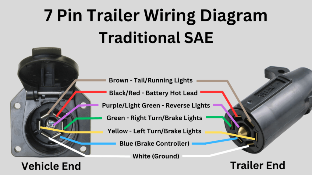
Traditional SAE Trailer Wire Color Codes
- Green Wire – right brake light and right turn signal
- Yellow Wire – left brake light and left turn signal
- Brown Wire – running lights and tail lights
- White Wire – ground wire that gives excess electrical charges a safe place to go
- Blue Wire – brake power and/or electric brake control
- Black or Red Wire – battery hot lead and 12V auxiliary power
- Light Green or Purple Wire – Reverse lights
While these codes are universal, you may find that the wiring colors vary slightly on some vehicle makes and models.
The Dodge Ram is one of these models where the wiring configuration is a bit different from that of the universal color coding found in most other vehicles.
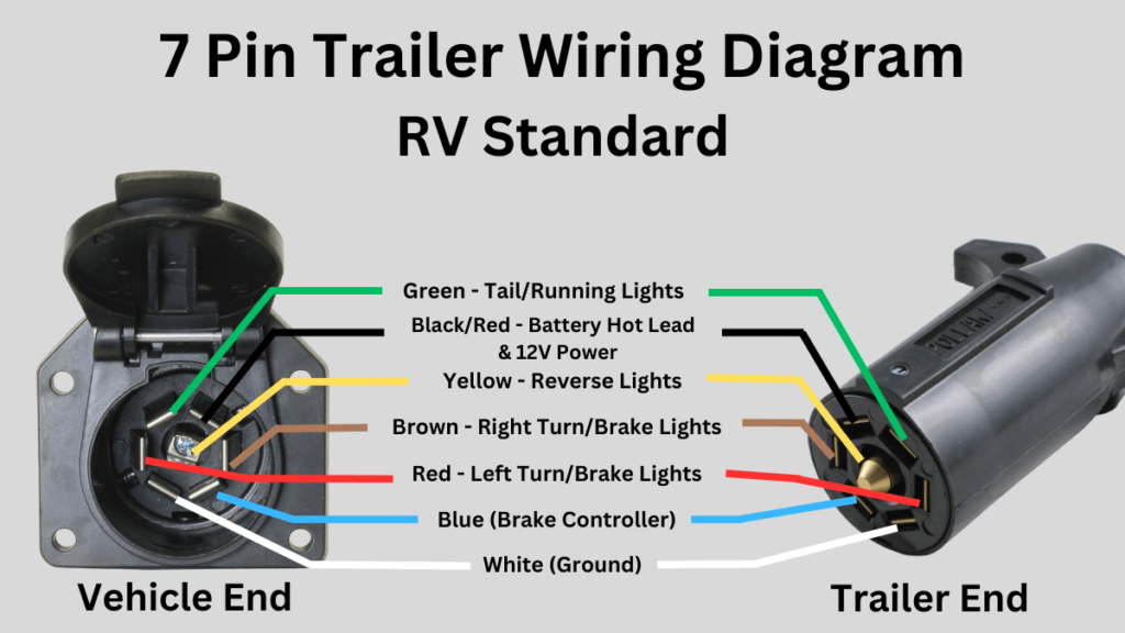
RV Standard Trailer Wire Color Codes
While the wiring in your standard RV trailer will be mostly the same colors as those found in your traditional SAE trailer, many of the wire colors will serve a different purpose.
- Green Wire – running lights and tail lights
- Yellow Wire – Reverse lights
- Brown Wire – right brake light and turn signal
- Black Wire – battery hot lead and 12V auxiliary power
- Red Wire – left brake light and turn signal
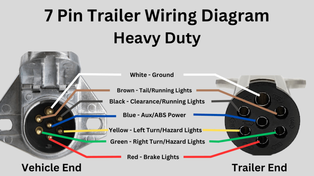
Heavy Duty Trailer Wire Color Codes
- Green Wire – right turn signal and hazard light
- Yellow Wire – left turn signal and hazard light
- Brown Wire – tail lights and running lights
- Blue Wire – brake power/control and aux power
- Black Wire – clearance and running lights
- Red Wire – brake lights
7 Pin Trailer Wiring Diagrams
Below are the 7 pin trailer wiring diagrams for each of the three main types of trailers.
Even if your wiring color codes do not match up with that of the universal color coding listed earlier, the functions of each of the wires (regardless of color) will still match up with the same pins in the wiring diagram.
7 Pin Trailer Wiring Diagram – Traditional SAE
7 Pin Trailer Wiring Diagram – RV Standard
7 Pin Trailer Wiring Diagram – Heavy Duty
7 Pin Trailer Wiring
The 7 pin trailer connector is by far the most common trailer connector there is these days, and is universal with pretty much any make and model of vehicle.
If you’ve bought a trailer somewhat recently, there’s a very good chance it features this 7 pin connector plug.
To accommodate this, most modern vehicles that feature a trailer hitch also come equipped with a 7 way connector socket near the hitch where the trailer connector plugs in and syncs all the electrical components.
If you have an older trailer or vehicle, you may find that you have one of the following connectors rather than the standard 7 pin connection:
- Four-way wiring connection
- Five-way wiring connection
- Six-way wiring connection
If you find that you have one of these non-standard connectors on your vehicle or trailer but also a 7 pin connector on the other end, you’ll need to do one of two things:
- Use an adapter that can sync the two different types of connectors, which is the easiest option.
- Convert the non-standard connector to a 7 pin connector by replacing it, which is the more difficult option.
Before syncing your vehicle with your trailer, it’s important to know which type of trailer you’re using and the functions of each of the different colored wires on the trailer connectors which can be found above.
Three Main Types of Trailers
There are three main types of trailers, all with slightly different colored wiring and connectors.
- Traditional SAE
- RV Standard
Traditional SAE – this is going to be the most common trailer you’ll find and include utility trailers, equipment trailers, or cargo trailers.
If you’re pulling a boat, off-road vehicle, or hauling materials of some sort this will most likely be what you’re using to do so.
RV Standard – if you’re pulling an RV, this is likely going to be what you’re using.
Heavy Duty – these are going to be your commercial or agricultural trailers, used for tougher jobs and to carry very heavy loads.
If you’re using a flatbed trailer to tow construction materials (think lumber, steel, heavy machinery), a dump trailer (stones, gravel, soil), or car hauler trailers to tow one or multiple vehicles, this is likely what you’re using.
While each trailer type is similar in terms of their different wiring connections, there are some slight differences as well.
Confirming Your Wiring Configuration
If you suspect that your wiring configuration is not universal, or if some or all of the trailer functions don’t seem to be working when connected, you can confirm what each wire does with the help of a circuit tester.
If you don’t seem to be getting a signal from the wires when using a circuit tester, check the fuse box under the hood of your vehicle to ensure the necessary fuses for the towing connection are installed.
If you’re looking to sync a trailer with your Chevy truck , occasionally these fuses will not be installed from the factory and you’ll need to take care of it on your own for the trailer functions to properly sync.
It’s highly important when towing a trailer behind your vehicle that each function is working correctly to ensure safe travel.
While electrical work can be intimidating for those of all experience levels, this 7 pin trailer wiring diagram should make it easier on you.
Your guide for All things off-road.
Follow us on social!
© Offroad official 2024
.png "travel trailer wiring colors")
FREE SHIPPING ON $150+ ORDERS
RV Trailer Wire Diagrams: How to Wire Your Trailer the Right Way
Learn how to wire your trailer so you can seamlessly use all electric appliances in your trailer as well as tow the trailer effectively.

Embarking on a road trip adventure in your RV is exciting, but don’t forget to make sure your RV’s systems are in order before hitting the road! One critical aspect often overlooked is the correct wiring of your recreational vehicle. A well-wired trailer not only promotes safety on the road but also ensures that your lights, brakes, and signals function seamlessly.
From powering appliances to maintaining essential safety systems, understanding the ins and outs of RV wiring is a must for any enthusiast. Whether you're a seasoned traveler or a novice hitting the open road, your RV’s electrical system is complex and requires attention. Lucky for you, we have covered everything you need to know and get in order before you set out. Take a read below so that you can navigate the process with confidence and enjoy a stress-free journey ahead!
The Importance of Proper RV Wiring
Proper RV wiring is more than just a technicality; it's the backbone of a safe and functional road trip experience. Without accurate and well-maintained wiring, you risk a host of problems that can quickly turn your adventure into a nightmare. Safety comes first, and correctly wired systems ensure that crucial functions like lights, brakes, and electrical appliances work seamlessly. This not only safeguards you and your fellow travel companions but also other motorists on the road. Other than that, efficient wiring maximizes energy usage, saving power and ultimately extending the lifespan of your RV's components.
Different Types of RV Trailers and Wiring Needs
The diverse world of RV trailers encompasses a wide range of options, each with unique wiring needs. When it comes to wiring requirements, travel trailers are a popular choice for those who prefer versatility and mobility. A typical travel trailer often utilizes a 30-amp RV 7-way trailer wiring diagram to handle essential systems like lighting, brakes , and appliances while smaller trailers operate with a 5-wire trailer connector and even a 2-wire trailer connector. These trailers are designed to be compact and lightweight, making them suitable for a 30-amp electrical supply.
On the other hand, fifth-wheel trailers cater to a more luxurious camping experience , requiring a robust 50-amp RV trailer plug wiring diagram to accommodate larger appliances, air conditioning units , and advanced entertainment systems. The substantial power requirements of these trailers make the 50-amp RV plug a vital component in ensuring all amenities function smoothly.
Additionally, the specific wiring requirements can vary based on the age and make of the RV trailer. Older models may require updates and renovations to bring their wiring systems up to modern safety and technology standards. Vintage Airstream trailers, for example, often need comprehensive overhauls to support modern conveniences. In contrast, newer RV trailers are typically equipped with advanced RV trailer wiring harnesses and the usual 2 trailer hitch ball mount, designed to handle high-tech devices and provide enhanced convenience.
Whether you're towing an older model or a brand-new luxury RV trailer, understanding the distinct wiring needs is crucial to ensure your trailer is not only functional but also optimized for the level of comfort and convenience you desire during your travels. So, considering the type of RV trailer and its age is vital in determining the wiring requirements, whether it's a 7 pin RV trailer wiring diagram, 4 wire trailer connector, or a 5 wire trailer wiring to 7 pin setup.
Basic Components of RV Trailer Wiring Systems
Before diving in, it is important to know just what you are dealing with. These components collectively form the backbone of an RV trailer's wiring system, whether you're dealing with a 30 amp RV wiring diagram or a 50 amp RV plug wiring diagram. Understanding these elements is essential for maintaining, troubleshooting, and ensuring the safe operation of your RV trailer during your travels. Give a quick read below to get a gist of the components in the system!
7-Way Connector:
The 7-way connector is a pivotal component that links the trailer's wiring to the tow vehicle. It consists of seven pins, each serving a specific purpose. These pins are numbered and color-coded for easy identification, ensuring the proper connection of power and signals between the RV trailer and the towing vehicle. One essential function of a 7-pin trailer plug is to charge the RV’s battery as it's being towed, ensuring that the trailer's electrical system remains operational.
Wiring Harness:
An RV trailer wiring harness is a network of cables and wires that extends throughout the RV trailer. It includes various wires for lighting, brakes, battery charging, and auxiliary power. This harness ensures a systematic and organized distribution of electricity from the 7-way connector to the trailer's components.
Trailer Wire Adaptor Connector:
A trailer wire adapter connector is a necessary component for the RV trailer wiring system as it helps to bridge the gap between different towing vehicles and trailers. This device ensures compatibility between various 2-wire trailer connectors and the towing vehicle's wiring.
Hitch Ball:
The hitch ball is crucial because it's the direct point of connection between the tow vehicle and the RV trailer. It ensures a secure link, allowing the trailer to be towed safely and effectively. Selecting the correct ball size for trailers is imperative, even for gooseneck trailers for safe towing as an incorrect size can lead to an unstable connection and potential accidents on the road.
Ball Mount:
A 2-trailer hitch ball mount plays a vital role in maintaining the level of the trailer when attached to the tow vehicle. Proper leveling is essential for safe towing because it ensures that the trailer's weight is distributed evenly, preventing issues like swaying or excessive strain on the tow vehicle's suspension.
Auxiliary Power Circuit:
The auxiliary power circuit in the 7-way connector is a versatile feature. It allows the trailer to draw power from the tow vehicle for various purposes, such as running interior appliances or charging auxiliary batteries. This added flexibility ensures that the trailer can meet a range of power requirements.
Ground Wire:
A ground wire is a fundamental part of the RV trailer wiring system. It connects to the metal frame of the trailer, creating a secure ground path for the electrical system. Proper grounding minimizes the risk of electrical issues, ensuring that the various components and systems function reliably and safely.
A Guide to Wiring Your Trailer the Right Way
With so many components and wires to keep track of, you won’t be the only person who gets confused. Follow our step-by-step guide below to make better sense of the process. By understanding the specific wiring needs of your trailer, you can wire your trailer correctly, whether it's a 5-wire trailer wiring to 7-pin setup or any other configuration. Here's a 10-step guide you on how to wire a 7-pin trailer plug the right way:
Step 1: Gather Tools and Materials
Ensure you have all the necessary tools, including wire cutters, crimping tools, heat shrink tubing, and materials like the appropriate gauge wire, a 5-pin trailer plug or a 5-pin to 7-pin trailer plug, and other trailer hitch ball accessories.
Step 2: Determine Wiring Needs
Understand your trailer's wiring needs based on its type and size. This could involve a travel trailer with a 30 amp RV wiring diagram or a travel trailer with a 50 amp RV plug wiring diagram, depending on the trailer's electrical demands.
Step 3: Locate the 7-Way Connector
Identify the ideal location on your trailer for mounting the 7-way connector. This should be easily accessible and near the rear for connection to the tow vehicle.
Step 4: Prepare the Wires
Trim and strip the wire ends for clean connections. Ensure you use the correct wire colors based on standard coding: red (12V power), green (right turn/brake), yellow (left turn/brake), white (ground), and so on.
Step 5: Connect the Wires
Connect the stripped wires to their respective pins on the 7-pin trailer plug. Use crimp connectors for a secure connection, ensuring a snug fit and good conductivity.
Step 6: Protect the Connections
Slide heat shrink tubing over the crimped connections and apply heat to seal and protect the wires from moisture and corrosion. Ensure a watertight seal.
Step 7: Secure the Wiring
Use zip ties or clamps to secure the wiring along the trailer frame. Prevent loose wires that could be damaged or drag on the road.
Step 8: Ground Wire Installation
Attach the white wire, which is the ground wire, securely to the trailer frame. Ensure a clean and rust-free connection point.
Step 9: Test the Wiring
Before hitting the road, test all the connections. Verify that all lights, turn signals, brakes, and other electrical components work correctly. A trailer wire adapter connector can be helpful for compatibility with your tow vehicle's wiring.
Step 10: Secure the 7-Way Connector
Mount the 7-way connector securely in its designated location on the trailer. Ensure it is protected from the elements and won't become disconnected during travel.
RV Trailer Wiring Diagrams
Here are some common trailer wiring diagrams for your reference.
RV 7 Way Trailer Wiring Diagram

4 Wire Trailer Connector Diagram

RV 7 to 6 Trailer Wiring Diagram

RV 7 to 5 Trailer Wiring Diagram

RV 7 to 4 Trailer Wiring Diagram

RV 4 to 4 Trailer Wiring Diagram

Common Mistakes to Avoid in Trailer Wiring
If you are new to understanding the wiring system of your RV, you are bound to make some mistakes. Ensuring proper trailer wiring is essential for safe and trouble-free towing. To help you avoid common mistakes, here are five pitfalls to steer clear of when working on your trailer's electrical system:
Inadequate Grounding:
A frequent mistake in trailer wiring is neglecting the importance of proper grounding. Failing to establish a solid ground connection between the trailer's wiring and the frame can lead to erratic electrical behavior. Ensure that the white wire (ground) is securely attached to a clean, rust-free part of the trailer frame, providing a reliable path for the current to return to the battery.
Incorrect Wire Sizing:
Using the wrong gauge of wire is another common error. The wire size should match the electrical load and distance it needs to travel as an inadequate wire gauge can lead to voltage drop and insufficient power to your trailer's components. To know what size wire you need for the trailer wiring systems, check the manufacturer's recommendations or refer to the RV wiring diagram.
Neglecting Weatherproofing:
Failing to protect your connections and wiring from the elements is a recipe for trouble. Exposed wires and connections can quickly corrode or short-circuit when exposed to moisture. Use heat shrink tubing or electrical tape to seal and protect your connections, ensuring they remain dry and corrosion-free.
Poor Cable Management:
Untidy and loosely secured wiring is not just unsightly; it can also be dangerous. Wires that dangle or drag on the road can get damaged or pose a safety hazard. Use zip ties or cable clamps to secure the wiring along the trailer frame, keeping it away from moving parts and road debris.
Incorrect Wiring Order:
Reversing the wiring order or improperly connecting the wires to the trailer plug is a common mistake. This can result in erratic lighting, non-functional brakes, or even electrical damage to your tow vehicle. Always consult a 7-pin RV trailer wiring diagram or the manufacturer's guidelines to ensure the proper connection of wires to the trailer plug.
Safety Tips to Keep in Mind When Wiring Your Trailer
Remember, at the end of the day, you are dealing with electrical wires and a complicated system. It is prone to accidents, sparks, unseen issues, and a multitude of other problems. By following these 5 safety tips when wiring a trailer, you can significantly reduce the risk of accidents.
Disconnect Power Sources:
Before starting any wiring work, ensure that all power sources are disconnected. This includes unplugging the tow vehicle, disconnecting the trailer from the vehicle, and disconnecting any batteries that may be part of the trailer's electrical system. This precaution eliminates the risk of electrical shock or short circuits during the installation or repair process.
Eye Protection and Gloves:
Wearing appropriate personal protective equipment is crucial. Safety glasses or goggles can protect your eyes from potential debris and wire ends. Additionally, insulated gloves are essential to minimize the risk of electrical shock while working with wires and connections.
Work in a Dry Environment:
Wiring tasks should be performed in a dry environment. Moisture and wet conditions can lead to electrical hazards, so it's essential to avoid working on your trailer's wiring during rainy weather. If you must work in damp conditions, take extra precautions to keep all connections dry and use waterproof sealants.
Use the Right Tools and Materials:
Using the proper tools and materials is essential for safety. Make sure your wire cutters, crimping tools, and connectors are in good condition and appropriate for the job. When making connections, use heat shrink tubing or electrical tape to insulate and protect the wires, and choose high-quality components and materials to ensure a reliable and safe trailer wiring system. Also make sure to learn beforehand what size wire you need for the trailer wiring and what size ball you need for your trailer, especially for a gooseneck trailer, so that you don’t encounter these issues after you start wiring your trailer.
Double-Check Your Work:
After completing the wiring, it's crucial to double-check your work for any loose connections, exposed wires, or potential issues. Test all the trailer's lights, brakes, and signals to ensure they function correctly. It's better to identify and rectify any issues before hitting the road, reducing the risk of accidents or breakdowns during your journey.
In the world of RV traveling, trailer wiring and safety are paramount. Your guide to a comfortable journey begins with ensuring a solid, secure electrical foundation. With proper grounding, the right tools, and a vigilant eye for detail, you're on your way to a world of comfort and adventures.
- How To's
Recent Posts
10 Travel Trailer Renovation Tips on a Budget
Backing Up a Trailer: A Guide
Mounting a TV in an RV: All You Need to Know
Trailer Wiring Diagram and Color Chart
How to install new wiring or repair a bad connection
- Cars & Motorcycles
- Frugal Living
- Fine Arts & Crafts
- Card Games & Gambling
- Playing Music
Whether you're installing a new trailer light circuit in your car or truck or trying to troubleshoot trailer wiring that is not working, you'll need to understand what each wire in the trailer wiring harness does, where it likely goes, and why it may not be working well. This diagram shows the colors of a basic trailer wiring setup as well as what each wire is supposed to be connected to.
A Simple Closed System
While it's never a good idea to dive into a wiring project blind, trailer wiring is actually very simple to work on and troubleshoot . For the most part, the wiring harness that operates your trailer lights is a closed system. The only point of contact to the outside world (meaning the world that exists outside of the trailer itself) comes on the truck side of the four-prong connector (or seven-prong connector if you are using a higher end system for trailers with electric braking systems ). Even on the truck side, where the trailer wiring intersects with your vehicle's wiring harness, there are only four wires to deal with. When you're troubleshooting the trailer wires, be sure you do it one wire at a time, starting by checking your ground wire with a circuit tester .
Trailer Wiring Colors
The worst that usually happens with screwy trailer wiring is a blown fuse on the tow vehicle—or something wacky, like reversed turn signals or blinking brake lights. While none of these are things we look forward to when pulling a trailer, they are also easy to correct. These four colored wires make up your trailer's wiring system. Each connects to a different function:
- Brown wire to the tail or parking lights
- Green wire to right turn signal/brake light
- Yellow wire to the left turn signal/brake light
- White wire to common or chassis ground
When making your repairs or hooking up your trailer, you simply make sure these wires are running to the appropriate component as shown above.
Lights On, Always
Never put your trailer on the road with questionable wiring or a lighting system that is already known to be failing. As drivers slow down behind a vehicle that is pulling a trailer, they will often instinctively focus on the bright brake lights as a reference point for where to stop and how quickly the vehicle in front is stopping. If you've got bright, well functioning brake lights on the trailer, these lights will catch the attention of the drivers behind you, regardless of how much they are paying attention. If your trailer's lights are dim or nonexistent, those drivers will focus on the lights on your vehicle, which likely will not give them enough time to stop, which could result in an accident. While they might be deemed at fault, no one needs the headache of dealing with insurance companies—nor do you want whatever cargo you are carrying to be damaged or anyone to be injured.
Remember, pulling a trailer is never something to take lightly. Always be extra aware of everything going on around you, and give everyone the right of way.
- How to Repair or Install Trailer Wiring
- How to Find a Short Circuit
- What to Do If Your Rear Defroster Doesn't Work
- Cruise Control Not Working? 9 Potential Causes
- Car Charging System Check
- Toyota Camry Trouble Codes Procedure
- Diagnosing GM Converter Lock-Up Problems
- 10 Easy Steps to Install a New Car Stereo
- What to Do When Your Car Won't Start or Turn Over
- GM Convertor Lock-Up and the TCC Solenoid
- Troubleshooting Common Condenser Fan Problems
- ABS Brakes and the Facts
- How Electronic Throttle Control (ETC) Works
- How to Clean the ABS Wheel Sensor on Your Car
- Dash Lights: The Battery Light on Your Dashboard
- Chevy Silverado Ignition Timing Specifications

How To Wire A Trailer . . . Trailer Wiring Diagram . . . And More
So many wires . . . So many colors . . . And, so many kinds of trailer wiring connectors. Yikes! Where do I start? I need a trailer wiring diagram. And, a little more information to make sure I get all the wires right!

The wiring approach for you depends on your electrical needs. To start, every trailer needs lights – brake lights, turn signals, and tail lights. Some also need side markers and running lights. Some brakes need electricity too – to actuate electric brakes, or to disable hydraulic brakes when backing up.
The following trailer wiring diagram(s) and explanations are a cross between an electrical schematic and wiring on a trailer. We recommend these standards because they are pretty universal. That said, for specific situations, there are industrial standards for different connector styles and wire arrangements. It can get confusing, so if you don’t already have a specific standard in mind, follow these.

4-Pin Flat Connector
At a minimum, all trailers need at least 4 functions: Tail lights, Brake lights, Left & Right signals. 4 wires will give these functions, so the simplest scheme is a 4-pin connector.
The most common 4 wire connector is the 4-Pin Flat Connector as shown here. Trailers that use this are usually fairly light weight and don’t have brakes or other power accessories. It’s the most common style for “consumer” type trailers. Small utility trailers , light boat trailers, little campers, off-road trailers and many more use this traditional 4-Pin Flat connector.
Lighter Duty Trailer (No Brakes) = Use a 4-Pin Connector .
1 . White = Ground (See White Wire Notes below.) 2 . Brown = Tail Lights, Side Markers and Running Lights (See Brown Wire Notes below.) 3 . Yellow = Left Turn Signal & Left Brake Light 4 . Green = Right Turn Signal & Right Brake Light
Please see the Trailer Wiring Diagram and Connector Application Chart below. The 4-Pin connector only has the first 4 items listed. The rest you can ignore.

5-Pin Flat Connector
(Round style 5-Pin Connectors also exist.) Typically, the 5th wire (blue) is for electric trailer brakes, however, that is not always true. The 5th pin is not as standard as the first 4.
Trailers with capacity over 3000# Total Gross Trailer Weight should have brakes . That’s not mandatory everywhere, but it’s a good idea.
If a trailer has brakes, then it needs a connector with at least 5 wires. The 5th pin, a blue wire, gives power to operate the trailer brakes. (The 5th wire can also be used to disable hydraulic brakes when in reverse.)
Traditional Trailer + with Brakes = Use a 5-Pin Connector .
1-4 Wire the first 4 pins (White, Brown, Yellow, Green) just like the 4-pin connector above. 5 . Blue = Electric Brakes or Hydraulic Reverse Disable (See Blue Wire Notes below.)
In the Trailer Wiring Diagram and Connector Application Chart below, use the first 5 pins, and ignore the rest.
If your truck has a built-in 7-pin socket, but you only need 5 of the pins. Use the 7-pin connector anyway (see below), and just leave out the last 2 wires. It accomplishes the same thing for 5 wires, but with a connector that’s compatible with your truck. The 5-Pin flat connector above is nice for easy handling, but if your vehicle already has a 7-pin, just use it. It’s OK, within the standards, to leave out wires for your custom situation.
Also, worth noting, When Does My Trailer Need Brakes?

7-Pin Connector
For trailers that have a little more going on electrically, we recommend 7-pin connectors. The 2 added pins are typically for Auxiliary Power and Back-up Lights .
Expanded Use Trailer + with Brakes, Aux Power & Back-up Lights = 7-Pin Connector . (6-Pin Connectors also exist, but they are less common.)
1-4 Wire the first 4 pins just like above, and the 5th line goes to the brakes. 5 . Blue = Electric Brakes or Hydraulic Reverse Disable (See Blue Wire Notes below.) 6 . Red (or Black) = 12V Auxiliary Power (See Red Wire Notes below.) 7 . Purple = Back-up Lights (Sometimes another color.)
7-Pin Connectors like the one pictured are very common for RV’s and other bigger-ish trailers. This is the style we recommend. Other styles exist — though the pin-outs are often different. Several industrial styles are similar and definitely use different pins.
It is OK to leave a pin or two blank (unused and unconnected). For instance, looking at the trailer wiring diagram, if you want Auxiliary Power, but don’t have back-up lights, then just leave the purple wire out. A blank spot (unconnected pin) doesn’t hurt anything.
The Trailer Wiring Diagram and Connector Application Chart

Single Axle Trailer Wiring

Tandem Axle Trailer Wiring
Typical Trailer Wiring Diagram and Schematic
The 2 above wire diagrams fit the needs of most trailers. The first image shows a single axle trailer, and the second, wiring for Tandem Axles. Only the (blue) brake and (white) ground wires are different. You can expand the same conditions for more axles.
Use only the needed wires, and ignore the others. For example, if you don’t need Auxiliary Power , just leave it out. If the axles do not have brakes, then no need for that. Don’t change pin numbers or wire positions if a function is not used — just leave the pin blank (not connected).
Three Center Marker Lights
The above trailer wire diagrams don’t show the triple set of marker lights central on the front and back. Some trailers need them, and some do not. Check local ordinances for requirements.

For trailers in the USA: Typically a red 3 light set is required on the back, if the trailer is 80″ or wider – or – if over 10,000 lbs GVWR. Also, near the top in the back if taller than a certain amount. An amber 3 light set is required near the top in the front, if taller than a certain amount (usually some amount over the height of the tow vehicle). Again, check regional requirements.
Typically the 3 center marker lights are at a high point on the trailer — like above the back doors for an enclosed cargo trailer. They are fine on the back bumper of a flatbed trailer, even when the load is much higher. There are lots of extras in the laws (like top corner markings), so find out what you need for your specific trailer.
If you need the more marker lights, connect them on the Brown and White wires just like the side marker lights. (See the partial trailer wiring diagram.) These do not require additional connections at the hitch, just more wiring within the trailer. These lights should be ‘on’ basically all the time.
Side Note: Reflectors
In addition to the three center marker lights, most trailers over 80″ width require reflectors or reflective tape in alternating red and white on the sides and back. There are a lot of regulations here for height, and GVWR, especially when trailers are longer than 20′. I’m not sure about requirements outside of the USA.
Check your local jurisdiction so you can mark and light your trailer properly. Reflectors and reflector types change by jurisdiction. To some, this is overkill, but even if it is, making it right can save you a ton of legal hassle and trouble.
Trailer Breakaway Wiring Diagram

If you have electric brakes (or electric over hydraulic or some others), then it will involve the trailer wiring. Here is a partial wiring diagram to include your trailer breakaway system. Since there is a lot to discuss, we have an entire article about breakaway kits with lots more information. In the meantime, use this diagram to guide the wiring of the system. Superimpose this on the images above to see how it all comes together.
The breakaway system usually resides in, on, or under the front part of the trailer. The pin pull switch is near the hitch. The system hooks into the electrical system by connecting Auxiliary Power (Red wire +12 VDC) to keep the battery charged, the Brakes (Blue wire) to actuate the brakes, and Ground (White wire) to complete the circuit. Again, please see the article about breakaway systems for a lot more information.
Wire Routing
Where do the wires go? Now that we have the trailer wiring diagram and some definition for connectors, where do the wires actually go?
Nestle the wires into and around the frame where practical for protection. We do recommend protecting the wires with a covering of some sort. The cover is not in the trailer wiring diagram, but flexible conduit, plastic conduit, or other approaches are great. A covering does not need to be watertight, but do consider weather protection when splicing into the wires. For tips on wiring, splicing, routing and protecting, see our post on trailer lights and wires . See more in the Wire Routing Notes below.

This photo shows an ideal way to handle trailer wires. While the flexible sealed conduit nestles in and secures to the frame, it protects the wires from snags and from weather. Great job on this one.
Trailer Wiring Diagram Notes
Many different sizes of wires are available. Typically wire sizes are list by “Gauge” — a smaller number is a thicker wire. We recommend 16 gage and larger for lighting. Then, for power hungry things like brakes, use a thicker wire size, like 14 gauge or 12 gauge. Same for Auxiliary Power.
Lighting circuits with low power lights like LED’s have low power requirements, so even with a lot of lights, they don’t use much power. For lights, a relatively small wire gage works. We still recommend 16 gage and larger, not so much because of the power requirements, but because the wires are stronger, more robust, and have more surface area for splice connections. It’s worth the small additional expense.
We recommend sealed and submersible LED lights for just about everything. Yeah, most trailers are never submersed, but almost all get very wet like in heavy rain or when washing. Pay the extra dollar or two and get the higher quality lights. Trouble free operation with higher quality lights make them worth it.
White Wire Notes:
The White Wire is the “Ground” or “Negative” wire connecting to the vehicle battery “minus” side. The trailer wiring diagram shows this wire going to all the lights and brakes. Also, it must connect with things (if included) that use the Aux Power and Back-up lights too.
Some trailer builders just connect this wire to the frame, then connect the ground from all the other lights and accessories to the frame as well. While this usually works, the ground portion of the circuit is often the root of trailer electrical problems. To avoid some of those issues we recommend running the white wire with all the others and connecting the ground from each light directly to the White. It is a little more work, but it can save big headaches later.
We also recommend connecting the white wire directly to the trailer frame (in addition).
Size: This wire should be at least as big as the largest wire in your harness. If only lights are in the circuit, and the lights are LED (low power), then a small white wire is acceptable. However, if you have electric brakes or auxiliary power, this wire must be larger.
Brown Wire Notes:
The Brown Wire goes to the lights that are always ON as you travel. These are the running lights, the low intensity portion of the tail lights, side markers, and corner markers. Also, if used, the sets of 3 lights central in front and back of the trailer. Check local laws for requirements on which lights your trailer needs.
While the typical sets of 3 lights central in the trailer are not in the above trailer wiring diagram, they are important in some situations. They are not normal for smallish DIY utility type trailers. However, if you need them or want them, the brown wire feeds them too (and the white for ground). Tiny Houses may or may not need the 3 lights, but again, check local laws.
Size: The Brown wire only feeds power to lights, so size it for the power requirements of your lights. For a utility trailer, that is probably not much power, so a smaller gage is OK. For a large enclosed trailer with lots of running lights, consider a larger gage.
Yellow and Green Wire Notes:
The two wires, Yellow and Green, handle double duty for function. They activate lights for both Turn Signals and for Brakes. It’s the same physical “light” at the rear of the trailer, but it serves 2 functions. The wiring in the vehicle sorts out how those signals are sent.
The Yellow wire handles the Left side – left as you look at the back of the trailer. (Or, in a different way of thinking, left as you are sitting in the driver’s seat of the tow vehicle.) The Green wire handles the Right side. See the above trailer wiring diagram for a visual.
Size: See the above discussion about Wire Size. We recommend 16 gage and larger for lights, and we recommend LED lights.
Blue Wire Notes:
Typically, the blue wire is for electric trailer brakes, however, this wire is not as standard as lights and ground.
For electric brakes, on the vehicle side the blue wire goes to the brake controller. Many styles of brake controllers are available, so find one that works for your vehicle. On the trailer side, the blue wire goes to the brakes and breakaway circuit. (See the trailer wiring & breakaway diagrams above.)
Here are some other ways the blue wire is sometimes used.
- Some trailers with surge hydraulic brakes use this 5th pin to disable the brakes when the vehicle is reversing. This is not in the trailer wiring diagram above. If you do this, then connect the blue wire to the reverse lights on the tow vehicle side, and be sure to note what you’ve done. Better yet, use a purple wire instead, and label it.
- Some places label the 5th pin for “Reverse Lights”. If you do that, then make sure to note it on the trailer, because it can cause a lot of trouble if connected wrong.
Just be careful when using a 5-pin connector. Make sure the car wires match functions of the trailer.
Compatibility Case Example: To solve issues with tow vehicle wiring that is different from my trailer (for instance when a friend wants to borrow it), I simply have a short adapter that connects the 5-pin harness to a 4-pin vehicle and the trailer goes without brakes. It works because the trailer is not big or heavy – and with a light load it does not require brakes. I just tell the borrower the load capacity is 3000# (even though true capacity is 5000#.) Another way is to have an adapter that goes from the trailer 5-pin to a standard 7-pin (with 2 wires left blank). That way the trailer brakes are ready, if the tow vehicle has a 7-pin connector.
Size: Don’t skimp on wire size for your brakes. For a single axle, 14 gage is good, but for tandem axles, use 12 gage wire.
Red Wire Notes:
The pin for Aux Power is usually with a Red Wire, but sometimes it’s different like Black. Sometimes we call it ‘Aux Power’ or ‘Auxiliary Power’ or ‘Accessory Power’ or ‘Batt 12V+’. Whatever the name it connects to the tow vehicle positive, DC power. Typically, auxiliary power is for charging the Breakaway battery, RV batteries, interior lights, power for accessories, etc.
The extent of routing for the Red wire is not on the above Trailer Wiring Diagram because it is optional, and different for every trailer. In the Breakaway wiring section, the schematic there shows how the Breakaway battery box connects to the Red. That maintains the battery charge.
If you don’t need separate power on the trailer, just leave that pin out. If you do use it, then be sure you protect the vehicle electric system from shorts (use a fuse or circuit breaker). Also, it’s good to protect the system from completely draining the tow vehicle battery.
Size: Use a wire size appropriate for the power demands. If it’s just for charging the breakaway battery, then 16 gage is fine. If you’re powering up more batteries or lights in the trailer, then use 14 or even 12 gage. Don’t overload this wire. If you do need large amounts of auxiliary power, use a generator or install special wiring from the vehicle alternator.
Wire Routing Notes:
The trailer wiring diagram above gives one flavor for routing direction – starting at the tongue connector, then wrapping around the trailer. Other people suggest splitting the wires near the tongue, then routing down both sides — Right and Left specific. Either approach is fine.
While wire routing is a personal preference, I like the wrap around approach a little more because it makes a ‘trunk’ that distributes power as it goes. It also keeps the wires all in one group as they traverse along the tongue so they are easier to protect. The amount of wire is almost identical for both the split and wrap around approach.
Protecting The Wires:
Hollow frame members are often the route for wires. For instance, if the frame is constructed of rectangular steel tube , then putting wires down the tube seems like an easy way to protect them. While this is true, it also means that you can’t cap (seal) the ends of the tube to keep moisture out. That’s a trade-off to consider, but it does not have to be all or nothing. On my last trailer, I routed the wires through the tongue tube, then outside the main frame members (tubes) so they can seal. Wire and light connections are outside of the frame tubes under the trailer bed.
When running wires consider the possibility of changes down the road. If you’re sure changes will never happen, button things up super tight. If you think changes might happen later, then leave access to the wires. For example, for a little camper, you might think Aux Power is on the “I’m never going to use that” list. But in a few years, you might find the solar doesn’t always cut it, and Aux Power is suddenly desirable. By leaving access to the wire routing, running the additional wire is not so difficult. Food for thought.
- You are here:
- Home »
- Blog »
- » DC 12v Black and White Wire (12v Wiring Color Coding Guide)

DC 12v Black and White Wire (12v Wiring Color Coding Guide)
- May 6, 2022 /
- RVing 101 /
- By James V.
The #1 rule when it comes to RV wiring is that there are no rules. What that means is that there are no real standards for colors when it comes to making RVs. This can be frustrating when you are upgrading a feature and the wire colors do not match up
The standard colors for 12 volt electrical systems are red is positive and black is negative. Sometimes RV makers change that standard and use the colors black and white with white being negative or ground. You never know what you will get when you open up an RV’s wiring system.
To find out more about this topic, just continue to read our article. it has the information you need to know about so you are not surprised or confused when upgrading electrical features in your RV. Take a few moments to see how this important information helps you and your wiring project.
12 Volt DC Wire Color Code
This will depend on the country or continent you are living in. The reason we bring the different codes to your attention is that while RVs are made in America and possibly Canada, not all products for RVs follow the American color code system
Then even the color code for America depends on the electrical wire system placed in RVs and products. For example, look at the table immediately below:
**data taken from https://www.allaboutcircuits.com/textbook/reference/chpt-2/wiring-color-codes/
As you can see there can be some confusion when you go to the wire in different products for your RV. The link under the table will also explain the color codes for Europe, Asia, Canada, and so on. While Canada has the same basic DC power system, the colors are often different from the American style.
What Does a 12v Black And White Wire Mean?

According to the NEC, the black wire is supposed to be the hot or positive wire. The white is supposed to be the negative wire. The green wire is supposed to be the ground wire.
This is the code that the NEC expects all American manufacturers to comply with. Then any wire with a marking, dotted line, etc., is supposed to be a positive wire. A black and white-colored wire is supposed to be a positive wire.
Only those wires with no markings are used for negative or ground. The markings are for your reference only and the markings and colors. They provide guidance so you have a consistent wire set up as long as you connect both ends to the correct terminals. If you don’t you could get a shocking surprise.
Also, you should follow the manufacturer’s instructions. If they say to use a particular wire and color at a specific terminal, then follow their instructions. What this means is that at one point a white wire can be both positive and negative.
What is a White Wire in 12V?

Generally and in theory, the white wire is supposed to be for the negative terminals. The reality is that you could possibly use any color wire for that function. RV makers have taken that freedom to new heights and often you do not see the color you expect connecting the negative terminals.
This can be confusing as there are codes they should be following but RV makers seem to make up their own codes as they go along. For example wires with stripes and dashes are supposed to be positive and wires with solid colors are supposed to be negative.
But when you look at your car’s DC system you will see that both colors of wires are solid. That has been the way it has been for over 100 years. There are products that will use solid colored wires for both sides of the electrical system. that is what everyone expects until they buy an RV or a product made in a different country.
In reality, you can use any color wire wherever you want as long as you hook both sides up to the same circuit. In other words, if you are using green as the negative it needs to be hooked to both negative connections. One end cannot be positive and one cannot be hooked to the negative side.
Wires are wires but the color-coding helps you avoid trouble.
12v Red And Black Wires

If everyone followed the color codes for wiring the world would be a safer place and less confusing. For a DC electrical system red is supposed to be positive and black is supposed to be negative.
That definition helps you when you buy a spool of wire that has the red and black wires molded into one wire. By that we mean that they are separate wires it is just the insulation that is joined together.
All you have to do is separate the joined wires and connect them red to positive and black to negative. But what if you have a stereo that uses yellow wire? If it is a solid color, it should be a negative wire but you cannot always be sure of that fact because most manufacturers do not follow color codes.
RV makers may use brown or the fan they installed uses brown and you bought a new fan that uses red, black, or green. It can be confusing and sometimes you have to use a multimeter to figure out which wire goes where.
As we research this topic, we are finding out that manufacturers do not care what color they use. Most likely, they will go with a color that costs them less and use that instead.
RV 12-volt Wiring Colors

It is said that the RV electrical system is partly an off shoot of the house electrical system. That means that black is supposed to be positive and the white color is supposed to be negative or the ground wire.
However, that is the ideal. RV makers do not subscribe to the ideal and make up their own codes. For example, Forest River uses striped duplex wires with white as the negative and the striped wire as the positive. Those stripes can be any color Forest River wants to use.
But. RV makers may use another color in place of the white when wiring clearance lights, etc. There really is no rhyme or reason for the way RV makers install and use wires. Sometimes the only way to tell which wire is which is by getting your multimeter out and doing some checking.
The table above gives the correct color codes but the NEC does not seem to be an enforcement body so no punishments will be handed out if the RV maker chooses to ignore those codes.
Your guess will be as good as ours if the RV and products manufacturers choose to use a different system.
Is black And White Wire Positive or Negative?

Yes! isn’t that a frustrating answer? You would think that the word Yes would not be answering this question and is meant only to confuse you and have a laugh at your expense. But that conclusion would be wrong.
The term Yes is the correct answer to that question. Sometimes the black wire is positive and sometimes the white is positive. Plus sometimes the black wire is negative and sometimes the white wire is negative.
Sometimes the white is a neutral wire or the ground wire, while black may not be used at all. When it comes to RVs, it is a real guessing game. The best thing to do is create a nice wire diagram for your current RV and keep it in a safe place. that way you will have a reference in case you forget which wire is which.
You can also use tape or stick-on numbers to help you identify which wire does what. Just make sure to record what color tape or which number you use don which wire.
Some Final Words
You may not know it by the above content but there are color codes that are supposed to be followed. There are several reasons why those codes are ignored. If you are unsure about where those colored wires go and if they are hot or not, pull out your multimeter and begin testing.
That will be the safest way to do your wiring project. Or make a diagram so you do not have to do testing the next time.
Related Posts
Does CarMax Buy RVs? (CarMax RV Trade-In Guide)
300 Lbs Over Payload: What Happens If I Exceed My Payload?
Thor Vegas Problems (Windshield, Battery, Fridge, Swivel Chair)
Leave a Comment:
Expert RV Wiring Tutorial: Wires, Connectors, and Tools
- Description
Do you feel clueless when it comes to RV wiring? Well, we’ve got good news. Most people do, too. Even better news? It’s simple to learn! Once you master the process, you can save a ton of time and money by wiring your RV’s lighting and appliances on your own.
The trick to safe and effective RV wiring is investing in the proper components. When you ensure you have the right wires, connectors, and tools for the task at hand, you set yourself up for a quick and stress-free project. In this lesson, we’ll teach you the basics of RV wiring, giving you a short rundown on the things to expect when you stop by your local hardware store to pick up the essentials.
RV Wiring: What You’ll Need and How to Use It
The rules of RV wiring are few, but they are vital. For a 12-volt (DC) system to function optimally, you must create proper connections. A poor connection means an inefficient or even hazardous system. To help you complete your first RV wiring job safely and effectively, RV expert Dave Solberg and RVCA Master Technician Steve Albright walk you step by step through an RV wiring demonstration.
To begin, Steve talks about the various specs of a high-quality wire, explaining the difference between a high-gauge flexible wire and a low-gauge rigid wire. He introduces a range of electrical situations for which you might choose one type of wire over another and stresses the importance of picking the correct wires, tools, and connectors for the job.
Once you know which components you’ll utilize during the process, it’s time to strip the wires and connect them. Steve demonstrates a sample connection using an inline fuse and finely braided wires. He also shows you how to strengthen a connection with an insulating shrink wrap tube, and explains a few circumstances when you might use alternative terminals to connect your RV wiring. With Steve’s quick tips for expert wiring, you’ll have your lighting and appliances hooked up in a flash!
Explore videos by RV Lifestyle & Repair Editors
You may be interested in
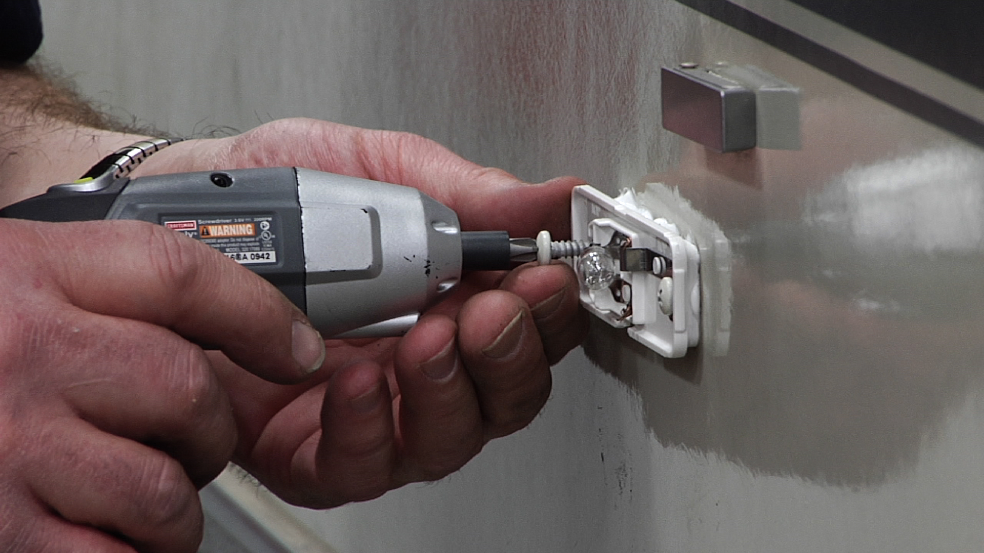
Premium Membership
Unlock exclusive member content from our industry experts.
- 24/7 Access to Premium RV Maintenance Videos, Travel Inspiration, and Lifestyle Tips
- Step-by-Step Instructional Demos, Projects, and Guides
- 50% Off Video Downloads Purchased in the RV Lifestyle & Repair Shop
- Access to Ask the Expert Program
- 2 Full-Length Video Downloads to Watch Offline
Gold Membership
Get everything included in Premium plus exclusive Gold Membership benefits.
- 9 Full-Length Video Downloads to Watch Offline
- 2 Full-Length RV Repair Classes to Keep for Life
- Discounts on Purchase-to-Own Content in the RV Lifestyle & Repair Shop
- Exclusive GOLD LIVE Streaming Events
Username or email *
Remember me
Lost your password?
Privacy Policy
Your cart is empty
Have an account?
Log in to check out faster.
Have Questions or concerns about your order? Call Us now at (833) 910 3416 !
The Trailer Parts Outlet ships ground orders predominately with FedEx. Ground orders ship next business day if ordered by 12PM CST. ( Some exclusions may apply )
Need shopping help?
Log into your account
Manage orders and track shipping
SHOPPING CART
Contact us now.
Have Questions or concerns about your order? Call Us now at (833) 910 3416!
Trailer Parts Experts

Jason Trailer Parts Expert
Call or Text: (936) 312-3337
Email: [email protected]

Trevor Trailer Parts Expert
Call or Text: (936) 349-6220
Email: [email protected]

Krystal Trailer Parts Expert
Call or Text: (936) 218-1280
Email: [email protected]

Kyle Trailer Parts Expert
Call or Text: (936) 226-3664
Email: [email protected]
Customer Service

Anna Customer Service Specialist
Call or Text: (936) 220-4199
Email: [email protected]
What do the Colors on 7-Way Trailer Light Wiring Mean?
Picture this. You have a worn-out wire or some other electrical failing, and some savvy trailer knowledge or clever Googling on your part has taught you that you have 7-way trailer wiring.
But sadly, every wire is a different color, and you have no idea why. Let’s learn classic color coding for your trailer so you can get your lights shining again with minimal…sparks.
So grab a wiring kit , and some properly gauged wire , and let’s get to work.
Two Types of Wiring to Know: SAE Standard or RV Standard
The color coding on your harness is going to vary depending on whether you’ve got a trailer or an RV. Trailer wiring is designed in accord with the practices of the Society of Automotive Engineers, or SAE.
Color Coding for SAE Standard Trailer Light Wiring
- Green: Right turn/brake light
- Yellow: Left turn/brake light
- Brown: Tail/running lights
- White: Ground wire
- Blue: Brake controller output
- Black: Battery hot lead
- Purple: Reverse lights
Color Coding for RV Standard Lights Wiring
- Green: Tail/running lights
- Yellow: Reverse Lights
- Brown: Right turn/brake light
- Blue: Brake cont
- roller output
- Red: Left turn/brake light
What if I don’t know which I have?
Let’s say you bought a used trailer with tons of unlicensed DIY work. You can always determine which wire is which using a circuit tester. That should help you figure out the intended function of each wire. Also, if you have some non-standard harness, you should definitely choose this option.
What Size Wiring for a 7-Way Wiring Harness
Generally, the smallest recommended size for a 7-way trailer plug is 16 gauge on turn signals, brake and reverse lights, and the running light wires. But go with 12 gauge for grounding, brake power, and battery hot lead wires.
More Questions About 7-Way Trailer Light Wiring?
Call or contact The Trailer Parts Outlet. We sell nation-wide, but our Texas hospitality comes through in every call. We know everything about trailer parts and wiring, so we’re happy to help no matter what snarl of wires you’re faced with, or no matter how many outlets you need replaced.
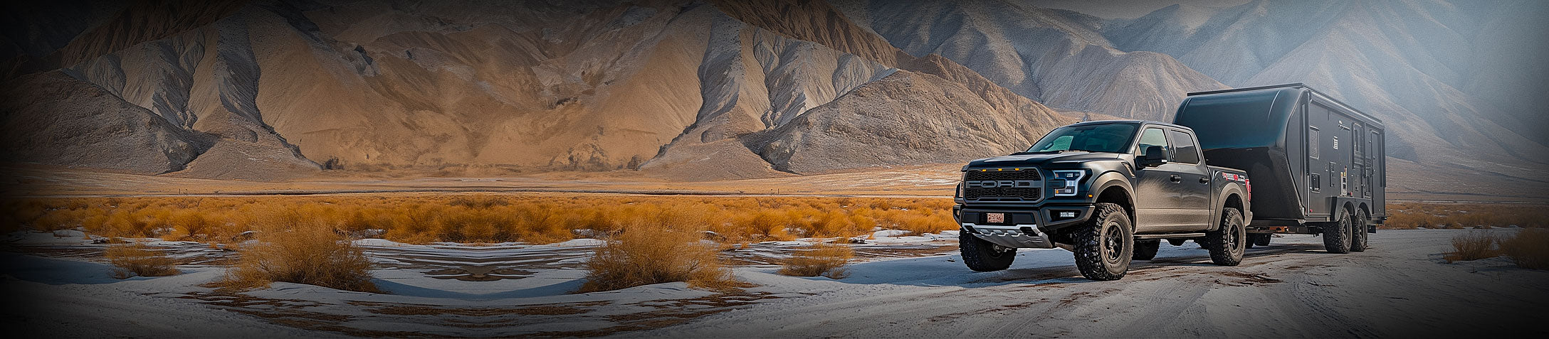
SIGN UP FOR OUR NEWSLETTER!
Learn about our products, weekly sales, discount codes and so much more.
- Choosing a selection results in a full page refresh.
- Opens in a new window.
IMAGES
VIDEO
COMMENTS
RV standard plug wiring is commonly used on travel trailers and campers in North America (so you can call it 7-pin trailer plug wiring diagram usa). If your trailer light wiring appears disorganized and you really don't know which trailer wire does what, using a circuit tester pen for identification would be a wise approach.
An RV wiring color code is a standardized system of colors used to identify the different functions and purposes of wires in an RV electrical system. This code is essential for ensuring that the correct wires are connected to the appropriate components and devices, and to prevent any potential electrical hazards or malfunctions.
Learn how Keystone's EXCLUSIVE color-coded 12V wiring is different from conventional RV wiring and why it's a better for both owners and service technicians. Easy-to-trace circuits help dealer service techs troubleshoot and complete repairs more quickly, saving owner's time and money. Clearly labeled wiring helps savvy owners with DIY ...
What Color Is the Hot Wire in an RV? Our RV wiring for dummies guide includes understanding what color is the hot wire. A hot wire is a cable that always carries the electrical current. The National Electrical Code (NEC) recognizes black as the hot wire in RVs and many other applications.
This trailer wiring guide comes complete with a color coded trailer wiring diagram for each plug type, including a 7 pin trailer wiring diagram, this guide walks through various trailer wiring installation solution, including custom wiring, splice-in wiring and replacement wiring. If your vehicle is not equipped with a working trailer wiring harness, there are a number of different solutions ...
We'll unravel the details of an RV's electrical system, review its components and their functions, and how it all comes together to power your home on wheels. Table of Contents hide. 1) RV Wiring for Dummies. 2) AC vs DC Power in an RV. 2.1) Alternating Current (AC Power) 2.1.1) AC Voltage. 2.1.2) AC Power Sources.
Trailer Wiring Connectors. Various connectors are available from four to seven pins that allow for the transfer of power for the lighting as well as auxiliary functions such as an electric trailer brake controller, backup lights, or a 12V power supply for a winch or interior trailer lights. Choose a connector that has the required number of ...
There are 2 conflicting 12v standards. Marine and automotive use red = +, black = - (ground). RV is an offshoot from house AC. Black = +, white = - (ground). Any pre-wired marine or car accessory will have black and red wires coming out of it. FR "electricians" will use RV wiring to complete the circuit (usually).
In the case of the 5-core connector, the 5 individual trailer wire colors signify different things. 1) The white color signifies the ground. 2) The brown color means tail lights or possible side markers. 3) The yellow color indicates a left turn signal light. 4) The green color signifies a right turn signal or light.
Standard wire color codes are essential for maintaining consistency and clarity in trailer wiring. Commonly recognized color codes include: Brown: Tail, running, and side marker lights. Yellow: Left turn signal and brake lights. Green: Right turn signal and brake lights. White: Ground wire for the electrical system.
7 Pin Trailer Wiring Diagrams. Below are the 7 pin trailer wiring diagrams for each of the three main types of trailers. Even if your wiring color codes do not match up with that of the universal color coding listed earlier, the functions of each of the wires (regardless of color) will still match up with the same pins in the wiring diagram.
In this video, I cover pitfalls to avoid when wiring your trailer lights, including:- differences in RVIA/NFPA1192 and SAE J2803 color codes- color code and...
An RV plug wire diagram is a visual representation of the electrical connections and wiring configuration needed for a recreational vehicle (RV). It outlines the specific wire colors, pin placements, and functions for each individual plug or connector within the RV's electrical system. The diagram serves as a guide for anyone trying to ...
This could involve a travel trailer with a 30 amp RV wiring diagram or a travel trailer with a 50 amp RV plug wiring diagram, depending on the trailer's electrical demands. ... Ensure you use the correct wire colors based on standard coding: red (12V power), green (right turn/brake), yellow (left turn/brake), white (ground), and so on.
The most common wire colors used in a 7-wire trailer wiring system are brown, yellow, green, white, red, blue, and black. Brown wire: This wire is typically used for the tail lights and clearance lights. Yellow wire: The yellow wire usually connects to the left turn signal and left brake light.
These four colored wires make up your trailer's wiring system. Each connects to a different function: Brown wire to the tail or parking lights. Green wire to right turn signal/brake light. Yellow wire to the left turn signal/brake light. White wire to common or chassis ground. When making your repairs or hooking up your trailer, you simply make ...
4-Pin Flat Connector. At a minimum, all trailers need at least 4 functions: Tail lights, Brake lights, Left & Right signals. 4 wires will give these functions, so the simplest scheme is a 4-pin connector. The most common 4 wire connector is the 4-Pin Flat Connector as shown here.
RV 12-volt Wiring Colors. It is said that the RV electrical system is partly an off shoot of the house electrical system. That means that black is supposed to be positive and the white color is supposed to be negative or the ground wire. However, that is the ideal. RV makers do not subscribe to the ideal and make up their own codes.
7-ways are some of the most common harnesses found on trailers. 7-ways provide the required running lights, turn signals, brake lights, and ground for the trailer. In addition, they provide three additional pins for a 12V hot lead, electric brakes, and reverse lights. Trailer wiring can be one of the most intimidating components of your towing ...
You may be interested in. Expert RV Wiring Tutorial: Wires, Connectors, and Tools Join RV Repair Club to continue watching for $10.00 per month / $98.00 per year. Learn the basics of RV wiring to create connections for the lighting and appliances of your RV. Find out which wires, connectors, and tools you'll need.
So grab a wiring kit, and some properly gauged wire, and let's get to work. Two Types of Wiring to Know: SAE Standard or RV Standard. The color coding on your harness is going to vary depending on whether you've got a trailer or an RV. Trailer wiring is designed in accord with the practices of the Society of Automotive Engineers, or SAE.
There are 2 conflicting 12v standards. Marine and automotive use red = +, black = - (ground). RV is an offshoot from house AC. Black = +, white = - (ground). Any pre-wired marine or car accessory will have black and red wires coming out of it. FR "electricians" will use RV wiring to complete the circuit (usually).
Boat Steering Systems. Trailer wiring is a topic that may seem complicated but it's crucial for safe towing. This trailer wiring guide will walk you through everything you need to know about trailer wiring. From the basic w.