Small Business Productivity, Tools and Tips – Android and iPhone Sync
What radio waves can travel through and what they cannot.
When Guglielmo Marconi began research into long-range radio in the late 19th century, the scientific community was skeptical. That he succeeded in transmitting radio signals more than 2000km met with much astonishment. What he had unwittingly done was discover the ionosphere, a layer in the atmosphere that is ionized to a degree by the sun’s ultraviolet rays.

This affects radio waves and reflects them to earth, which bounces them upwards again. This repeated sequence enables us to transmit radio waves around the world. So, if radio waves can’t penetrate the ionosphere, what else will hinder them? Let’s look at what radio waves consist of, and then we’ll talk about their ability or otherwise to pass through certain materials.

Radio Waves Explained
Developments in radio technology have brought us a long way in the past 100 years and more, but how do radio waves work? Before Marconi’s discovery, scientists believed that radio signals could only travel a straight line, as they were known to do in free space. Hence, there was a necessity for tall towers from which to transmit signals. A 100m high tower, for example, could send a signal up to around 30km, the limit set by the curvature of the earth. Marconi showed that radio waves could be bent and bounced by the ionosphere.
Radio waves form a small part of what is known as the electromagnetic spectrum (EMS). This consists not just of radio waves but also other forms of electromagnetic radiation such as gamma rays, microwaves, visible light, and more. Radio waves have among the longest wavelengths on the EMS. Imagine a rope held between two people. Move the rope up and down at one end, and a waveform moves across the rope.
This is what a radio wave would look like if we could see it. The wavelength is the distance between two ‘peaks’ in the wave. We also have to consider the frequency, which the number of waves that pass a given point in a set time. This is vital to understand so that different transmissions do not interfere with each other.
Television signals are radio waves, but they are broadcast in a different frequency range to the radio.
What has this to do with the materials that radio waves can and cannot pass through? Let’s look more closely at this.

What Can’t Radio Waves Pass-Through?
We’ve already seen that radio waves do not penetrate the ionosphere. We should explain that this refers to radio waves of up to 40MHz, the highest frequency bounced off the ionosphere. Why do radio waves bounce back?
As we mentioned, the ionosphere is partly ionized.
This is because the UV light from the sun causes electrons to shake free from atoms, leaving a large proportion of free electrons hanging about in the ionosphere. When a radio wave hits the ionosphere, the energy created by the free electrons, as a result, causes the radio waves to be repelled or reflected.
So, we know that radio waves up to 40MHz won’t pass through an ionized layer in the atmosphere. Remember that we explained the perceived limitations of radio transmissions before Marconi’s discovery. A line of sight was necessary, without obstructions, for successful transmission.
In some radio transmissions, interference can be caused by the waves being blocked by materials that they cannot penetrate. While radio waves can move through wood, bricks, and concrete to a certain extent, these materials can still cause interference. This is because radio waves meeting such objects can be reflected from buildings and other large structures, just like the ionosphere. This explains why the reception of radios and other radio frequency devices such as smartphones vary between locations.
For the record, as it covers a large bandwidth necessarily, television signals need to be above 40MHz so they cannot be bounced off the ionosphere, hence the tall towers in high locations used for TV transmissions.
Radio waves will also be adversely affected by metal and water, which they cannot pass through. That is because water and metal are both electrical conductors. Like the ionosphere, metal and water contain many free electrons, which will vibrate when a radio wave hits the surface, and the wave will bounce back.
To summarize, we now know that radio waves are affected by free electrons in electrical conductors such as metals and water and cannot pass through these materials.
We have discovered that they can pass through non-conducting materials quite well but are losing propagation power with reflecting surfaces such as water, metal, and other materials. Furthermore, worldwide radio transmission is made possible by the radio waves being reflected by the ionosphere and the earth in a continuous sequence, allowing for transmissions to be made across great distances.
You are using an outdated browser. Please upgrade your browser to improve your experience and security.

- PERSPECTIVES
- Military & Aerospace
- AI & Big Data
- Power Management
- Industrial Control & Automation
- Programmable Logic
- Prototyping
- Test & Measurement
- Wireless & Networking
- Silicon Grapevine
- Wine Down Friday
- Education Link
- EETimes University
- Tech Papers
- Asia Pacific
- Europe / Middle East
- Special Projects
RF Basics: Radio Propagation
Radio wave propagation.
It is fitting in a book about wireless communication to look at the phenomena that lets us transfer information from one point to another without any physical mediumâthe propagation of radio waves. If you want to design an efficient radio communication system, even for operation over relatively short distances, you should understand the behavior of the wireless channel in the various surroundings where this communication is to take place. While the use of “brute force” increasing transmission power could overcome inordinate path losses, limitations imposed on design by required battery life, or by regulatory authorities, make it imperative to develop and deploy short-range radio systems using solutions that a knowledge of radio propagation can give.
The overall behavior of radio waves is described by Maxwell’s equations. In 1873, the British physicist James Clerk Maxwell published his Treatise on Electricity and Magnetism in which he presented a set of equations that describe the nature of electromagnetic fields in terms of space and time. Heinrich Rudolph Hertz performed experiments to confirm Maxwell’s theory, which led to the development of wireless telegraph and radio. Maxwell’s equations form the basis for describing the propagation of radio waves in space, as well as the nature of varying electric and magnetic fields in conducting and insulating materials, and the flow of waves in waveguides.
From them, you can derive the skin effect equation and the electric and magnetic field relationships very close to antennas of all kinds. A number of computer programs on the market, based on the solution of Maxwell’s equations, help in the design of antennas, anticipate electromagnetic radiation problems from circuit board layouts , calculate the effectiveness of shielding, and perform accurate simulation of ultra-high-frequency and microwave circuits. While you don’t have to be an expert in Maxwell’s equations to use these programs (you do in order to write them!), having some familiarity with the equations may take the mystery out of the operation of the software and give an appreciation for its range of application and limitations.
The Four Types of Radio Wave Propagation
What are the four types of radio wave propagation? Radio waves can propagate from transmitter to receiver in four ways: through ground waves, sky waves, free space waves, and open field waves. Ground waves exist only for vertical polarization, produced by vertical antennas, when the transmitting and receiving antennas are close to the surface of the earth. The transmitted radiation induces currents in the earth, and the waves travel over the earth’s surface, being attenuated according to the energy absorbed by the conducting earth. The reason that horizontal antennas are not effective for ground wave propagation is that the horizontal electric field that they create is short circuited by the earth.

Ground wave propagation is dominant only at relatively low frequencies, up to a few MHz, so it needn’t concern us here. Sky wave propagation is dependent on reflection from the ionosphere, a region of rarified air high above the earth’s surface that is ionized by sunlight (primarily ultraviolet radiation).
The ionosphere is responsible for long-distance communication in the high-frequency bands between 3 and 30 MHz. It is very dependent on time of day, season, longitude on the earth, and the multiyear cyclic production of sunspots on the sun. It makes possible long-range communication using very low power transmitters. Most short-range communication applications that we deal with in this chapter use VHF, UHF, and microwave bands, generally above 40 MHz. There are times when ionospheric reflection occurs at the low end of this range, and then sky wave propagation can be responsible for interference from signals originating hundreds of kilometers away. However, in general, sky wave propagation does not affect the short-range radio applications that we are interested in.
The most important propagation mechanism for short-range communication on the VHF and UHF bands is that which occurs in an open field, where the received signal is a vector sum of a direct line-of-sight signal and a signal from the same source that is reflected off the earth. Later we discuss the relationship between signal strength and range in line-of-sight and open field topographies.
The range of line-of-sight signals, when there are no reflections from the earth or ionosphere, is a function of the dispersion of the waves from the transmitter antenna. In this free-space case the signal strength decreases in inverse proportion to the distance away from the transmitter antenna. When the radiated power is known, the field strength is given by equation (5.1):
Range can be calculated on this basis at high UHF and microwave frequencies when high-gain antennas are used, located many wavelengths above the ground. Signal strength between the earth and a satellite, and between satellites, also follows the inverse distance law, but this case isn’t in the category of short-range communication! At microwave frequencies, signal strength is also reduced by atmospheric absorption caused by water vapor and other gases that constitute the air.
Open Field Propagation
Although the formulas in the previous section are useful in some circumstances, the actual range of a VHF or UHF signal is affected by reflections from the ground and surrounding objects. The path lengths of the reflected signals differ from that of the line-of-sight signal, so the receiver sees a combined signal with components having different amplitudes and phases.
The reflection causes a phase reversal. A reflected signal having a path length exceeding the line-of-sight distance by exactly the signal wavelength or a multiple of it will almost cancel completely the desired signal (“almost” because its amplitude will be slightly less than the direct signal amplitude). On the other hand, if the path length of the reflected signal differs exactly by an odd multiple of half the wavelength, the total signal will be strengthened by “almost” two times the free space direct signal.
In an open field with fl at terrain there will be no reflections except the unavoidable one from the ground. It is instructive and useful to examine in depth the field strength versus distance in this case. The mathematical details are given in the Mathcad worksheet “Open Field Range.”
In Figure 5.1 we see transmitter and receiver antennas separated by distance d and situated at heights h 1 and h 2 . Using trigonometry, we can find the line of sight and reflected signal path lengths d 1 and d 2 . Just as in optics, the angle of incidence equals the angle of reflection θ. We get the relative strength of the direct signal and reflected signal using the inverse path length relationship. If the ground were a perfect mirror, the relative reflected signal strength would exactly equal the inverse of d 2 . In this case, the reflected signal phase would shift 180 degrees at the point of reflection. However, the ground is not a perfect reflector. Its characteristics as a reflector depend on its conductivity, permittivity, the polarization of the signal, and its angle of incidence.
5.1. Open field signal paths In the Mathcad worksheet we have accounted for polarization, angle of incidence, and permittivity to find the reflection coefficient, which approaches -1 as the distance from the transmitter increases. The signals reaching the receiver are represented as complex numbers, since they have both phase and amplitude. The phase is found by subtracting the largest interval of whole wavelength multiples from the total path length and multiplying the remaining fraction of a wavelength by 2Ï radians, or 360 degrees.
Figure 5.2 gives a plot of relative open field signal strength versus distance using the following parameters : Polarity: horizontal Frequency: 300 MHz Antenna heights: both 3 meters Relative ground permittivity: 15
5.2. Field strength versus range at 300 MHz Also shown is a plot of free space field strength versus distance (dotted line). In both plots, signal strength is referenced to the free space field strength at a range of 3 meters. Notice in Figure 5.2 that, up to a range of around 50 meters, there are several sharp depressions of field strength, but the signal strength is mostly higher than it would be in free space. Beyond 100 meters, signal strength decreases more rapidly than for the free space model. Whereas there is an inverse distance law for free space, in the open field beyond 100 meters (for these parameters) the signal strength follows an inverse square law. Increasing the antenna heights extends the distance at which the inverse square law starts to take effect. This distance, dm, can be approximated by
Part 2 will cover Multipath Phenomena Part 3 will cover Diversity Techniques
References Gibson, J. D. (ed.), The Mobile Communications Handbook, CRC Press, Inc., 1996. Rappaport, T. S., Wireless Communications, Principles and Practice, Prentice Hall, Upper Saddle River, NJ, 1996. Spix, G. J., “Maxwell’s Electromagnetic Field Equations,” unpublished tutorial, copyright 1995 (http://www.connectos.com/spix/rd/gj/nme/maxwell.htm).
Related Articles
- Low Latency Radio System Design Considerations
- John Hays Hammond, Jr. â Father of Radio Control
- James Clerk Maxwellâwas he the founder of Electrical Engineering?
- Paper: Pushing the Envelope of Wireless Communications
- All RF Articles
Copyright: Printed with permission from Newnes, a division of Elsevier. Copyright 2008. “RF & Wireless Technologies” by Bruce A. Fette. For more information about this title and other similar books, please visit www.newnespress.com.
Share this:
Leave a reply cancel reply.
You must Register or Login to post a comment.
This site uses Akismet to reduce spam. Learn how your comment data is processed .
RF Basics: Radio Propagation

It is fitting in a book about wireless communication to look at the phenomena that lets us transfer information from one point to another without any physical medium—the propagation of radio waves. If you want to design an efficient radio communication system, even for operation over relatively short distances, you should understand the behavior of the wireless channel in the various surroundings where this communication is to take place. While the use of “brute force” —increasing transmission power—could overcome inordinate path losses, limitations imposed on design by required battery life, or by regulatory authorities, make it imperative to develop and deploy short-range radio systems using solutions that a knowledge of radio propagation can give.
The overall behavior of radio waves is described by Maxwell’s equations. In 1873, the British physicist James Clerk Maxwell published his Treatise on Electricity and Magnetism in which he presented a set of equations that describe the nature of electromagnetic fields in terms of space and time. Heinrich Rudolph Hertz performed experiments to confirm Maxwell’s theory, which led to the development of wireless telegraph and radio. Maxwell’s equations form the basis for describing the propagation of radio waves in space, as well as the nature of varying electric and magnetic fields in conducting and insulating materials, and the flow of waves in waveguides.
From them, you can derive the skin effect equation and the electric and magnetic field relationships very close to antennas of all kinds. A number of computer programs on the market, based on the solution of Maxwell’s equations, help in the design of antennas, anticipate electromagnetic radiation problems from circuit board layouts, calculate the effectiveness of shielding, and perform accurate simulation of ultra-high-frequency and microwave circuits. While you don’t have to be an expert in Maxwell’s equations to use these programs (you do in order to write them!), having some familiarity with the equations may take the mystery out of the operation of the software and give an appreciation for its range of application and limitations.
Mechanisms of Radio Wave Propagation Radio waves can propagate from transmitter to receiver in four ways: through ground waves, sky waves, free space waves, and open field waves. Ground waves exist only for vertical polarization, produced by vertical antennas, when the transmitting and receiving antennas are close to the surface of the earth. The transmitted radiation induces currents in the earth, and the waves travel over the earth’s surface, being attenuated according to the energy absorbed by the conducting earth. The reason that horizontal antennas are not effective for ground wave propagation is that the horizontal electric field that they create is short circuited by the earth.
Ground wave propagation is dominant only at relatively low frequencies, up to a few MHz, so it needn’t concern us here. Sky wave propagation is dependent on reflection from the ionosphere, a region of rarified air high above the earth’s surface that is ionized by sunlight (primarily ultraviolet radiation).
The ionosphere is responsible for long-distance communication in the high-frequency bands between 3 and 30 MHz. It is very dependent on time of day, season, longitude on the earth, and the multiyear cyclic production of sunspots on the sun. It makes possible long-range communication using very low power transmitters. Most short-range communication applications that we deal with in this chapter use VHF, UHF, and microwave bands, generally above 40 MHz. There are times when ionospheric reflection occurs at the low end of this range, and then sky wave propagation can be responsible for interference from signals originating hundreds of kilometers away. However, in general, sky wave propagation does not affect the short-range radio applications that we are interested in.
The most important propagation mechanism for short-range communication on the VHF and UHF bands is that which occurs in an open field, where the received signal is a vector sum of a direct line-of-sight signal and a signal from the same source that is reflected off the earth. Later we discuss the relationship between signal strength and range in line-of-sight and open field topographies.
The range of line-of-sight signals, when there are no reflections from the earth or ionosphere, is a function of the dispersion of the waves from the transmitter antenna. In this free-space case the signal strength decreases in inverse proportion to the distance away from the transmitter antenna. When the radiated power is known, the field strength is given by equation (5.1):
where P t is the transmitted power, G t is the antenna gain, and d is the distance. When P t is in watts and d is in meters, E is volts/meter. To find the power at the receiver (P r ) when the power into the transmitter antenna is known, use (5.2):
G t and G r are the transmitter and receiver antenna gains, and λ is the wavelength.
Range can be calculated on this basis at high UHF and microwave frequencies when high-gain antennas are used, located many wavelengths above the ground. Signal strength between the earth and a satellite, and between satellites, also follows the inverse distance law, but this case isn’t in the category of short-range communication! At microwave frequencies, signal strength is also reduced by atmospheric absorption caused by water vapor and other gases that constitute the air.
Open Field Propagation Although the formulas in the previous section are useful in some circumstances, the actual range of a VHF or UHF signal is affected by reflections from the ground and surrounding objects. The path lengths of the reflected signals differ from that of the line-of-sight signal, so the receiver sees a combined signal with components having different amplitudes and phases.
The reflection causes a phase reversal. A reflected signal having a path length exceeding the line-of-sight distance by exactly the signal wavelength or a multiple of it will almost cancel completely the desired signal (“almost” because its amplitude will be slightly less than the direct signal amplitude). On the other hand, if the path length of the reflected signal differs exactly by an odd multiple of half the wavelength, the total signal will be strengthened by “almost” two times the free space direct signal.
In an open field with fl at terrain there will be no reflections except the unavoidable one from the ground. It is instructive and useful to examine in depth the field strength versus distance in this case. The mathematical details are given in the Mathcad worksheet “Open Field Range.”
In Figure 5.1 we see transmitter and receiver antennas separated by distance d and situated at heights h 1 and h 2 . Using trigonometry, we can find the line of sight and reflected signal path lengths d 1 and d 2 . Just as in optics, the angle of incidence equals the angle of reflection θ. We get the relative strength of the direct signal and reflected signal using the inverse path length relationship. If the ground were a perfect mirror, the relative reflected signal strength would exactly equal the inverse of d 2 . In this case, the reflected signal phase would shift 180 degrees at the point of reflection. However, the ground is not a perfect reflector. Its characteristics as a reflector depend on its conductivity, permittivity, the polarization of the signal, and its angle of incidence.
5.1. Open field signal paths
In the Mathcad worksheet we have accounted for polarization, angle of incidence, and permittivity to find the reflection coefficient, which approaches -1 as the distance from the transmitter increases. The signals reaching the receiver are represented as complex numbers, since they have both phase and amplitude. The phase is found by subtracting the largest interval of whole wavelength multiples from the total path length and multiplying the remaining fraction of a wavelength by 2π radians, or 360 degrees.
Figure 5.2 gives a plot of relative open field signal strength versus distance using the following parameters : Polarity: horizontal Frequency: 300 MHz Antenna heights: both 3 meters Relative ground permittivity: 15
5.2. Field strength versus range at 300 MHz
Also shown is a plot of free space field strength versus distance (dotted line). In both plots, signal strength is referenced to the free space field strength at a range of 3 meters. Notice in Figure 5.2 that, up to a range of around 50 meters, there are several sharp depressions of field strength, but the signal strength is mostly higher than it would be in free space. Beyond 100 meters, signal strength decreases more rapidly than for the free space model. Whereas there is an inverse distance law for free space, in the open field beyond 100 meters (for these parameters) the signal strength follows an inverse square law. Increasing the antenna heights extends the distance at which the inverse square law starts to take effect. This distance, dm, can be approximated by
where h 1 and h 2 are the transmitting and receiving antenna heights above ground and λ is the wavelength, all in the same units as the distance d m . In plotting Figure 5.2, we assumed horizontal polarization. Both antenna heights, h 1 and h 2 , are 3 meters. When vertical polarization is used, the extreme local variations of signal strengths up to around 50 meters are reduced because the ground reflection coefficient is less at larger reflection angles. However, for both polarizations, the inverse square law comes into effect at approximately the same distance. This distance in Figure 5.2 where λ is 1 meter is, from equation (5.3): d m _ (12 _ 3 _ 3)/ λ _ 108 meters. In Figure 5.2 we see that this is approximately the distance where the open-field field strength falls below the free-space field strength.
Part 2 will cover Multipath Phenomena Part 3 will cover Diversity Techniques
References Gibson, J. D. (ed.), The Mobile Communications Handbook, CRC Press, Inc., 1996. Rappaport, T. S., Wireless Communications, Principles and Practice, Prentice Hall, Upper Saddle River, NJ, 1996. Spix, G. J., “Maxwell’s Electromagnetic Field Equations,” unpublished tutorial, copyright 1995 (http://www.connectos.com/spix/rd/gj/nme/maxwell.htm).
Leave a Comment
You must be logged in to post a comment.

- Dogs Smell Cancer? – The Canine Nose Sniffs Out New Methods in Cancer Detection Technology
- Engineering Cinema: The Evolution of the Motion Picture Camera
- Shocking! – How Airplanes Defend Against Lightning
- How GPS Revolutionized Navigation
- Engineering a Masterpiece: The Science of Fresco Painting

USC Viterbi School of Engineering
Catch a Wave: Radio Waves and How They Work
About the Author: Andrew Schnickel
In Fall 2000, Andrew Schnickel was a Junior majoring in CECS who enjoyed running barefoot in the rain.
Introduction

You are driving down the open road, not a care in the world. It’s a sunny summer day and you have the car windows down. Everything seems almost perfect, yet something is missing. You turn on the radio, tune it to your favorite station (see Fig. 1), and instantly the car fills with sound. Suddenly, everything feels right. Radio is something most of us take for granted. Have you ever stopped to consider how a radio works? How does a radio know which station to play? What is AM, what is FM, and how are the two different? Why does FM sound better, but AM can be heard farther away? You have probably experienced a time when finding a particular radio station has been difficult. There are many factors involved in finding and receiving stations, factors such as modulation, broadcasting power, time of day, and geographical location. The key to getting the most out of your radio is to understand how radio works and how engineering has played a part in the development of a device which most of us use everyday.
Radio Basics
Am and fm differences.
Two characteristics, amplitude and frequency (see Fig. 2), mark the difference between AM and FM radio. AM stands for amplitude modulation, which means the amplitude of the radio signal is used to encode information. FM denotes frequency modulation, which uses a change in frequency to encode information. From this you can see that both AM and FM radio use modulation to encode information. “Modulation is the variation of some property of the radio carrier in a manner that conveys information” [1].
Modulation Explained
Amplitude modulation (am), frequency modulation (fm), sound quality and performance, signal strength, frequency range, interference, broadcast range.
- [1] J.J. Carr. “Elements of Electronic Communications.” Reston, Virginia: Reston Publishing Company, Inc., 1978.
- [2] R.S. Carson. “Radio Communications Concepts: Analog.” New York: John Wiley & Sons, 1990.
- [3] Editors and Engineers The “Radio” Handbook. Los Angeles: Editors and Engineers, 1942.
- ← Minerva: A Pioneer in Everyday Robots
- Fuel Injection →
Similar Posts

Chemical Engineering Your Dinner

Inside a Slot Machine

Engineering a Smooth Ride: Creating the Perfect Ski Through Shaping and Vibration Damping
Leave a reply cancel reply.
Your email address will not be published. Required fields are marked *
2 minute read
Radio Waves
Propagation of radio waves.
Radio waves travel by three different routes from their point of propagation to their point of detection. These three routes are through the troposphere, through the ground, and by reflection off the ionosphere. The first of these routes is the most direct. A radio wave generated and transmitted from point A may travel in a relatively straight line through the lower atmosphere to a second point, B, where its presence can be detected by a receiver. This "line of sight" propagation is similar to the transmission of a beam of light from one point to another on Earth's surface. And, as with light, this form of radio wave propagation is limited by the curvature of Earth's surface.
This description is, however, overly simplified. Radio waves are deflected in a number of ways as they move through the troposphere. For example, they may be reflected, refracted, or diffracted by air molecules through which they pass. As a consequence, radio waves can actually pass beyond Earth's optical horizon and, to an extent, follow Earth's curvature.
Line-of-sight transmission has taken on a new dimension with the invention of communications satellites. Today a radio wave can be aimed at an orbiting satellite traveling in the upper part of the atmosphere. That satellite can then retransmit the signal back to Earth's surface, where it can be picked up by a number of receiving stations. Communications satellites can be of two types. One, a passive satellite, simply provides a surface off which the radio wave can be reflected. The other type, an active satellite, picks up the signal received from Earth's surface, amplifies it, and then retransmits it to ground-based receiving stations.
Since radio waves are propagated in all directions from a transmitting antenna , some may reflect off the ground to the receiving antenna, where they can be detected. Such waves can also be transmitted along Earth's surface in a form known as surface waves. Radio waves whose transmission takes place in connection with Earth's surface may be modified because of changing ground conditions, such as irregularities in the surface or the amount of moisture in the ground.
Finally, radio waves can be transmitted by reflection from the ionosphere. When waves of frequencies up to about 25 megahertz (sometimes higher) are projected into the sky, they bounce off a region of the ionosphere known as the E layer. The E layer is a region of high electron density located about 50 mi (80 km) above Earth's surface. Some reflection occurs off the F layer of the ionosphere also, located about 120 mi (200 km) above Earth's surface. Radio waves reflected by the ionosphere are also known as sky waves.
Additional topics
- Radio Waves - Transmission Of Radio Waves
- Other Free Encyclopedias
Science Encyclopedia Science & Philosophy: Quantum electronics to Reasoning Radio Waves - Propagation Of Radio Waves, Transmission Of Radio Waves, Modulating A Sound Wave
December 22, 2011
Block Radio Waves
An electromagnetically charged challenge from Science Buddies
By Science Buddies
On supporting science journalism
If you're enjoying this article, consider supporting our award-winning journalism by subscribing . By purchasing a subscription you are helping to ensure the future of impactful stories about the discoveries and ideas shaping our world today.
Key concepts Physics Radio waves Electricity Electromagnetism Wireless communication Introduction Have you ever wondered how a radio can receive music and news broadcasts over thin air? Radios, as well as radio-controlled cars and cell phones, all receive information via invisible waves. Some of these waves are called radio waves. Radio waves are a type of electromagnetic radiation, a kind of energy that also includes visible light. Radio waves are not harmful but are in fact extremely useful for communicating across long distances. To send information using radio waves, a transmitting antenna sends out a radio wave at a certain frequency (which can tell us the size of the wave), and this is picked up by a receiving antenna. Some materials can block, or interfere with, radio waves. Have you ever noticed that you lose reception on a car radio or cell phone when you drive into a tunnel or an underground parking garage? What materials block the radio waves, and which ones allow the waves to easily pass through? Background A transmitting antenna, or transmitter, generates and sends out radio waves thanks to a specific electrical current. This is possible because inside transmitters are wires that allow negatively charged particles, called electrons, to flow through them, which makes an electrical current. When current flows within a wire, it generates an electromagnetic field around the wire. This electromagnetic field radiates out of the antenna in all directions, creating invisible radio waves. When the electromagnetic radio waves hit a receiving antenna, or receiver, such as a radio, it generates a current inside of a wire in the receiver. (The reverse process of what happened in the transmitter when the current generated the electromagnetic field in the first place.) The receiver then processes the current back into the transmitted information, which, for a radio, allows you to hear music or other broadcasts. Some materials can block the radio waves that the transmitter generates, which can be tested by seeing whether a receiver can process and respond to information sent by a transmitter. Materials • Radio-controlled car and its corresponding remote control (both with working batteries) • Cotton (such as a piece of clothing made from cotton) • Aluminum foil • Plastic wrap • Wax paper • Rubber glove • A smooth, wide open space to test drive your radio-controlled car Preparation • First check the radio-controlled car and its remote control to make sure they both have fresh batteries. Check that the car runs well on the open space that you will be using. • Make sure you have enough of each material you want to test (the cotton, aluminum foil, plastic wrap, wax paper, and rubber glove) to completely cover the RC car remote control. Every covering should be loose enough so you can still operate the remote control buttons through it. Procedure • Wrap the remote control in cotton. Make sure that the remote control is completely and securely covered so that there are not any openings or holes in the covering, and that it is covered loose enough so that you can still operate the controls. • Try to operate the radio-controlled car using the cotton-covered remote control. Does it work? Does the car move at all? • Remove the tested material from the remote control. Test to make sure that the car still works when it is not covered with any material. • Repeat this process using each different material separately. For which materials does the car still operate, and for which materials does the car not operate? Why do you think this is? • Extra: Are the wireless signals transmitted by other devices blocked by the same material(s) that you found could block the signals from the remote control in this activity? You can try this activity again but using other remote control devices, such as your TV or stereo remote. How do different wireless devices respond? Do you think they use similar or different types of waves? • Extra: Do you need to completely cover the radio-controlled car remote control to block its signal? Using the material(s) you found to block the signals from the remote control to the radio-controlled car, completely cover the remote control as you originally did in this activity, and then slowly remove the covering from the remote control while trying to operate the car. How much covering is needed to block the signal? Are some parts of the remote control more important to cover in order to block the signal? Observations and results Did covering the radio-controlled car remote control with aluminum foil stop the radio-controlled car from working? Did any of the other materials tested stop the car? When you operate the car using its remote control, the remote control transmits radio waves at specific frequencies that can be received by the car. The remote control acts as a transmitter and the car as a receiver. Then, when the car receives the radio waves, which are electromagnetic waves, the waves generate a current in a wire in the car, and this tells the car which direction to move in. Depending on a material’s thickness and composition, it might block—or interfere with—radio waves. Thin amounts of plastic wrap, wax paper, cotton and rubber are not likely to interfere with radio waves. However, aluminum foil, and other electrically conductive metals such as copper, can reflect and absorb the radio waves and consequently interferes with their transmission. Placing the transmitter or receiver in a fully enclosed container made of highly conductive metal, such as was done in this activity, is the most efficient way to interfere with radio waves. More to explore " Radio Waves Locate Water within Walls " from Scientific American A Science Odyssey: Radio Transmission from PBS Online Blocking Radio Waves from Newton: Ask A Scientist What are electromagnetic fields? from the World Health Organization Wave Blockers from Science Buddies This activity brought to you in partnership with Science Buddies
Suggestions or feedback?
MIT News | Massachusetts Institute of Technology
- Machine learning
- Sustainability
- Black holes
- Classes and programs
Departments
- Aeronautics and Astronautics
- Brain and Cognitive Sciences
- Architecture
- Political Science
- Mechanical Engineering
Centers, Labs, & Programs
- Abdul Latif Jameel Poverty Action Lab (J-PAL)
- Picower Institute for Learning and Memory
- Lincoln Laboratory
- School of Architecture + Planning
- School of Engineering
- School of Humanities, Arts, and Social Sciences
- Sloan School of Management
- School of Science
- MIT Schwarzman College of Computing
Wireless communication breaks through water-air barrier
Press contact :, media download.

*Terms of Use:
Images for download on the MIT News office website are made available to non-commercial entities, press and the general public under a Creative Commons Attribution Non-Commercial No Derivatives license . You may not alter the images provided, other than to crop them to size. A credit line must be used when reproducing images; if one is not provided below, credit the images to "MIT."

Previous image Next image
MIT researchers have taken a step toward solving a longstanding challenge with wireless communication: direct data transmission between underwater and airborne devices.
Today, underwater sensors cannot share data with those on land, as both use different wireless signals that only work in their respective mediums. Radio signals that travel through air die very rapidly in water. Acoustic signals, or sonar, sent by underwater devices mostly reflect off the surface without ever breaking through. This causes inefficiencies and other issues for a variety of applications, such as ocean exploration and submarine-to-plane communication.
In a paper being presented at this week’s SIGCOMM conference, MIT Media Lab researchers have designed a system that tackles this problem in a novel way. An underwater transmitter directs a sonar signal to the water’s surface, causing tiny vibrations that correspond to the 1s and 0s transmitted. Above the surface, a highly sensitive receiver reads these minute disturbances and decodes the sonar signal.
“Trying to cross the air-water boundary with wireless signals has been an obstacle. Our idea is to transform the obstacle itself into a medium through which to communicate,” says Fadel Adib, an assistant professor in the Media Lab, who is leading this research. He co-authored the paper with his graduate student Francesco Tonolini.
The system, called “translational acoustic-RF communication” (TARF), is still in its early stages, Adib says. But it represents a “milestone,” he says, that could open new capabilities in water-air communications. Using the system, military submarines, for instance, wouldn’t need to surface to communicate with airplanes, compromising their location. And underwater drones that monitor marine life wouldn’t need to constantly resurface from deep dives to send data to researchers.
Another promising application is aiding searches for planes that go missing underwater. “Acoustic transmitting beacons can be implemented in, say, a plane’s black box,” Adib says. “If it transmits a signal every once in a while, you’d be able to use the system to pick up that signal.”
Decoding vibrations
Today’s technological workarounds to this wireless communication issue suffer from various drawbacks. Buoys, for instance, have been designed to pick up sonar waves, process the data, and shoot radio signals to airborne receivers. But these can drift away and get lost. Many are also required to cover large areas, making them impracticable for, say, submarine-to-surface communications.
TARF includes an underwater acoustic transmitter that sends sonar signals using a standard acoustic speaker. The signals travel as pressure waves of different frequencies corresponding to different data bits. For example, when the transmitter wants to send a 0, it can transmit a wave traveling at 100 hertz; for a 1, it can transmit a 200-hertz wave. When the signal hits the surface, it causes tiny ripples in the water, only a few micrometers in height, corresponding to those frequencies.
To achieve high data rates, the system transmits multiple frequencies at the same time, building on a modulation scheme used in wireless communication, called orthogonal frequency-division multiplexing. This lets the researchers transmit hundreds of bits at once.
Positioned in the air above the transmitter is a new type of extremely-high-frequency radar that processes signals in the millimeter wave spectrum of wireless transmission, between 30 and 300 gigahertz. (That’s the band where the upcoming high-frequency 5G wireless network will operate.)
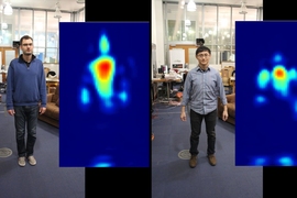
The radar, which looks like a pair of cones, transmits a radio signal that reflects off the vibrating surface and rebounds back to the radar. Due to the way the signal collides with the surface vibrations, the signal returns with a slightly modulated angle that corresponds exactly to the data bit sent by the sonar signal. A vibration on the water surface representing a 0 bit, for instance, will cause the reflected signal’s angle to vibrate at 100 hertz.
“The radar reflection is going to vary a little bit whenever you have any form of displacement like on the surface of the water,” Adib says. “By picking up these tiny angle changes, we can pick up these variations that correspond to the sonar signal.”
Listening to “the whisper”
A key challenge was helping the radar detect the water surface. To do so, the researchers employed a technology that detects reflections in an environment and organizes them by distance and power. As water has the most powerful reflection in the new system’s environment, the radar knows the distance to the surface. Once that’s established, it zooms in on the vibrations at that distance, ignoring all other nearby disturbances.
The next major challenge was capturing micrometer waves surrounded by much larger, natural waves. The smallest ocean ripples on calm days, called capillary waves, are only about 2 centimeters tall, but that’s 100,000 times larger than the vibrations. Rougher seas can create waves 1 million times larger. “This interferes with the tiny acoustic vibrations at the water surface,” Adib says. “It’s as if someone’s screaming and you’re trying to hear someone whispering at the same time.”
To solve this, the researchers developed sophisticated signal-processing algorithms. Natural waves occur at about 1 or 2 hertz — or, a wave or two moving over the signal area every second. The sonar vibrations of 100 to 200 hertz, however, are a hundred times faster. Because of this frequency differential, the algorithm zeroes in on the fast-moving waves while ignoring the slower ones.
Testing the waters
The researchers took TARF through 500 test runs in a water tank and in two different swimming pools on MIT’s campus.
In the tank, the radar was placed at ranges from 20 centimeters to 40 centimeters above the surface, and the sonar transmitter was placed from 5 centimeters to 70 centimeters below the surface. In the pools, the radar was positioned about 30 centimeters above surface, while the transmitter was immersed about 3.5 meters below. In these experiments, the researchers also had swimmers creating waves that rose to about 16 centimeters.
In both settings, TARF was able to accurately decode various data — such as the sentence, “Hello! from underwater” — at hundreds of bits per second, similar to standard data rates for underwater communications. “Even while there were swimmers swimming around and causing disturbances and water currents, we were able to decode these signals quickly and accurately,” Adib says.
In waves higher than 16 centimeters, however, the system isn’t able to decode signals. The next steps are, among other things, refining the system to work in rougher waters. “It can deal with calm days and deal with certain water disturbances. But [to make it practical] we need this to work on all days and all weathers,” Adib says.
“TARF is the first system that demonstrates that it is feasible to receive underwater acoustic transmissions from the air using radar,” says Aaron Schulman, an assistant professor of computer science and engineering at the University of California at San Diego. “I expect this new radar-acoustic technology will benefit researchers in fields that depend on underwater acoustics (for example, marine biology), and will inspire the scientific community to investigate how to make radar-acoustic links practical and robust.”
The researchers also hope that their system could eventually enable an airborne drone or plane flying across a water’s surface to constantly pick up and decode the sonar signals as it zooms by.
The research was supported, in part, by the National Science Foundation.
Share this news article on:
Press mentions, smithsonian magazine.
Smithsonian reporter Emily Matchar highlights how MIT researchers have developed a new system that enables data sharing between underwater and airborne devices. Prof. Fadel Adib explains that the technology could be used to “study marine life and have access to a whole new world that is still pretty much out of our reach today.”
IEEE Spectrum
Prof. Fadel Abid speaks with IEEE Spectrum reporter Michael Koziol about a new system his research group developed to enable communication between underwater sources and the air. “We’re very interested in how deep and how high you can go,” says Adib. “Even from a theoretical perspective, we don’t even know what the limits are.”
FOX News reporter Jamie Rogers writes that MIT researchers have developed a new system that “helps solve a longstanding problem in wireless communication – how to send data directly from a submarine to a plane or drone.”
MIT researchers have developed a new system that allows data to be transmitted between underwater and airborne devices, according to the BBC News. The system could enable submarines to communicate with planes, and in the future the device could “help planes or drones detect the location of a submerged ‘black box’ flight recorder.”
Popular Mechanics
Popular Mechanics reporter Avery Thompson describes a new method developed by MIT researchers to send signals between the water and the air by using sound waves to create detectable vibrations at the water’s surface. Thompson explains that the new technology could eventually make “exploring and living under the waves much easier.”
Engadget reporter Jon Fingas writes that MIT researchers have developed a new wireless device that allows data to be transmitted from an underwater source to the air. Fingas explains that the system could allow submarines to “send their findings directly to aircraft (including drones) circling above while remaining safely underwater, and without using boats as intermediaries.”
Previous item Next item
Related Links
- Project: Translational Acoustic-RF Communication (TARF)
- School of Architecture and Planning
Related Topics
- Ocean science
- National Science Foundation (NSF)
Related Articles

Wireless system can power devices inside the body

Drones relay RFID signals for inventory control
How wireless “X-ray vision” could power virtual reality, smart homes, and Hollywood

New system uses low-power Wi-Fi signal to track moving humans — even behind walls
More mit news.

Liftoff: The Climate Project at MIT takes flight
Read full story →

Bridging the heavens and Earth

MIT OpenCourseWare sparks the joy of deep understanding

A wobble from Mars could be sign of dark matter, MIT study finds

Enhancing LLM collaboration for smarter, more efficient solutions

Affordable high-tech windows for comfort and energy savings
- More news on MIT News homepage →
Massachusetts Institute of Technology 77 Massachusetts Avenue, Cambridge, MA, USA
- Map (opens in new window)
- Events (opens in new window)
- People (opens in new window)
- Careers (opens in new window)
- Accessibility
- Social Media Hub
- MIT on Facebook
- MIT on YouTube
- MIT on Instagram
Introduction to the Electromagnetic Spectrum
What is Electromagnetic energy?
Electromagnetic energy travels in waves and spans a broad spectrum from very long radio waves to very short gamma rays. The human eye can only detect only a small portion of this spectrum called visible light. A radio detects a different portion of the spectrum, and an x-ray machine uses yet another portion. NASA's scientific instruments use the full range of the electromagnetic spectrum to study the Earth, the solar system, and the universe beyond.
When you tune your radio, watch TV, send a text message, or pop popcorn in a microwave oven, you are using electromagnetic energy. You depend on this energy every hour of every day. Without it, the world you know could not exist.

Our Protective Atmosphere
Our Sun is a source of energy across the full spectrum, and its electromagnetic radiation bombards our atmosphere constantly. However, the Earth's atmosphere protects us from exposure to a range of higher energy waves that can be harmful to life. Gamma rays, x-rays, and some ultraviolet waves are "ionizing," meaning these waves have such a high energy that they can knock electrons out of atoms. Exposure to these high-energy waves can alter atoms and molecules and cause damage to cells in organic matter. These changes to cells can sometimes be helpful, as when radiation is used to kill cancer cells, and other times not, as when we get sunburned.
Atmospheric Windows

Electromagnetic radiation is reflected or absorbed mainly by several gases in the Earth's atmosphere, among the most important being water vapor, carbon dioxide, and ozone. Some radiation, such as visible light, largely passes (is transmitted) through the atmosphere. These regions of the spectrum with wavelengths that can pass through the atmosphere are referred to as "atmospheric windows." Some microwaves can even pass through clouds, which make them the best wavelength for transmitting satellite communication signals.
While our atmosphere is essential to protecting life on Earth and keeping the planet habitable, it is not very helpful when it comes to studying sources of high-energy radiation in space. Instruments have to be positioned above Earth's energy-absorbing atmosphere to "see" higher energy and even some lower energy light sources such as quasars.
Next: Anatomy of an Electromagnetic Wave
National Aeronautics and Space Administration, Science Mission Directorate. (2010). Introduction to the Electromagnetic Spectrum. Retrieved [insert date - e.g. August 10, 2016] , from NASA Science website: http://science.nasa.gov/ems/01_intro
Science Mission Directorate. "Introduction to the Electromagnetic Spectrum" NASA Science . 2010. National Aeronautics and Space Administration. [insert date - e.g. 10 Aug. 2016] http://science.nasa.gov/ems/01_intro
Discover More Topics From NASA
James Webb Space Telescope

Perseverance Rover

Parker Solar Probe

COMMENTS
$\begingroup$ The atmosphere allows the radio waves to bounce off it, as does the ground, allowing the waves to travel. $\endgroup$ - jhobbie. Commented Jun 25, 2014 at 19:29. 1 ... Radio waves will not travel through the Earth. It's just too dense for that. Think of it this way: when you take an x-ray, you can see your skeleton in detail in ...
Radio propagation is the behavior of radio waves as they travel, or are propagated, from one point to another in vacuum, or into various parts of the atmosphere. [1]: 26‑1 As a form of electromagnetic radiation, like light waves, radio waves are affected by the phenomena of reflection, refraction, diffraction, absorption, polarization, and scattering. [2]
Radio waves will also be adversely affected by metal and water, which they cannot pass through. That is because water and metal are both electrical conductors. Like the ionosphere, metal and water contain many free electrons, which will vibrate when a radio wave hits the surface, and the wave will bounce back.
The range of the ground wave (up to 1,600 km [1,000 miles]) and the bending and reflection of the sky wave by the ionosphere depend on the frequency of the waves. Under normal ionospheric conditions 40 MHz is the highest-frequency radio wave that can be reflected from the ionosphere.
What are the four types of radio wave propagation? Radio waves can propagate from transmitter to receiver in four ways: through ground waves, sky waves, free space waves, and open field waves. Ground waves exist only for vertical polarization, produced by vertical antennas, when the transmitting and receiving antennas are close to the surface ...
Radio waves have the longest wavelengths in the electromagnetic spectrum. They range from the length of a football to larger than our planet. Heinrich Hertz proved the existence of radio waves in the late 1880s. He used a spark gap attached to an induction coil and a separate spark gap on a receiving antenna. When waves created by the sparks of ...
Mechanisms of Radio Wave Propagation. Radio waves can propagate from transmitter to receiver in four ways: through ground waves, sky waves, free space waves, and open field waves. Ground waves exist only for vertical polarization, produced by vertical antennas, when the transmitting and receiving antennas are close to the surface of the earth.
Radio waves were first predicted by the theory of electromagnetism that was proposed in 1867 by Scottish mathematical physicist James Clerk Maxwell. [3] His mathematical theory, now called Maxwell's equations, predicted that a coupled electric and magnetic field could travel through space as an "electromagnetic wave".Maxwell proposed that light consisted of electromagnetic waves of very short ...
Ground wave is a mode of radio propagation that consists of currents traveling through the earth.Ground waves propagate parallel to and adjacent to the surface of the Earth, and are capable covering long distances by diffracting around the Earth's curvature. This radiation is also known as the Norton surface wave, or more properly the Norton ground wave, because ground waves in radio ...
Low frequency radio waves do not travel very far through the atmosphere and are absorbed rather quickly. ... In these areas there are few electrons to reflect radio waves and thus lower frequency waves are able to reach the ground. As can be seen from the animations the night time and early morning hours are best for observations due to the ...
Ground Wave Propagation: When RF signals travel along the Earth's surface, they experience ground wave propagation at lower frequencies encompassing the MF, LF, and VLF bands. At these frequencies, diffraction enables radio waves to curve over hills and obstructions, extending their reach beyond the visible horizon while adhering to the Earth's ...
First, radio waves can travel directly from one point to another. This is called line-of-sight propagation. The second way radio waves travel is along the ground, bending slightly to follow the curvature of the Earth for some distance. This is called ground-wave propagation. Third, radio waves can be refracted or bent back to Earth by the ...
Larger wavelength waves can travel farther because they can travel well through solid objects. FM radio waves on the other hand do not travel well through solid objects. This is the reason FM stations sometimes fade in and out when driving in mountainous areas. Another reason why AM radio waves can be heard far away is that they can be ...
A radio wave generated and transmitted from point A may travel in a relatively straight line through the lower atmosphere to a second point, B, where its presence can be detected by a receiver. ... such as irregularities in the surface or the amount of moisture in the ground. Finally, radio waves can be transmitted by reflection from the ...
Ground and Sky Waves Signals in the medium and shortwave bands travel by two basic means: ground waves and sky waves. Ground waves occur as the signal spreads out from the trans-mitter in all directions. Instead of traveling in a straight line (and not being heard beyond the visual horizon), radio signal tends to follow the curvature of the Earth.
21 1 2. Radio waves are electromagnetic in nature. Recall that EM waves do not require medium for propagation. The continuously changing electric field of an EM wave generates continuously changing magnetic field and vice versa. This is a never ending phenomenon. - Mitchell. Jun 2, 2017 at 12:36.
$\begingroup$ @zEyeland There can be radio waves and sound waves of the same frequency (low frequency radio waves and high frequency sound might both be found in the kHz range). You can't hear them because they're waves in the electromagnetic field, not in the pressure of the air. (Comments aren't a good place to ask questions. Let's wrap this up.
The remote control acts as a transmitter and the car as a receiver. Then, when the car receives the radio waves, which are electromagnetic waves, the waves generate a current in a wire in the car ...
Radio signals that travel through air die very rapidly in water. Acoustic signals, or sonar, sent by underwater devices mostly reflect off the surface without ever breaking through. ... The signals travel as pressure waves of different frequencies corresponding to different data bits. For example, when the transmitter wants to send a 0, it can ...
What is Electromagnetic energy? Electromagnetic energy travels in waves and spans a broad spectrum from very long radio waves to very short gamma rays. The human eye can only detect only a small portion of this spectrum called visible light. A radio detects a different portion of the spectrum, and an x-ray machine uses yet another portion.
Through-the-Earth (TTE) signalling is a type of radio signalling used in mines and caves that uses low-frequency waves to penetrate dirt and rock, which are opaque to higher-frequency conventional radio signals.. In mining, these lower-frequency signals can be relayed underground through various antennas, repeater or mesh configurations, but communication is restricted to line of sight to ...
1. The Basics. At its simplest, space communications relies on two things: a transmitter and a receiver. A transmitter encodes a message onto electromagnetic waves through modulation, which changes properties of the wave to represent the data. These waves flow through space toward the receiver. The receiver collects the electromagnetic waves ...
$\begingroup$ "GPR uses high-frequency (usually polarized) radio waves, usually in the range 10 MHz to 2.6 GHz." But penetrate is a misnomer. If you want a signal to travel through the Earth, it needs to be ELF at "3 to 30 Hz", or ULF at "0.3 to 3 kHz" (Extremely and Ultra Low Frequency, respectively