
- Fire Engineering Training

Elevators: Power Shunt Trip
Greg Havel discusses how an elevator’s power shunt trip, which is activated before automatic fire sprinklers discharge, could affect firefighting operations and how firefighters can deal with them.
Article and photos by Gregory Havel
The ASME and NFPA standards and codes consider the occupants of an elevator car that is stopped between floors or that is evacuated at the nearest floor level to be at less risk than they would be if the elevator continued to operate during fire sprinkler discharge.
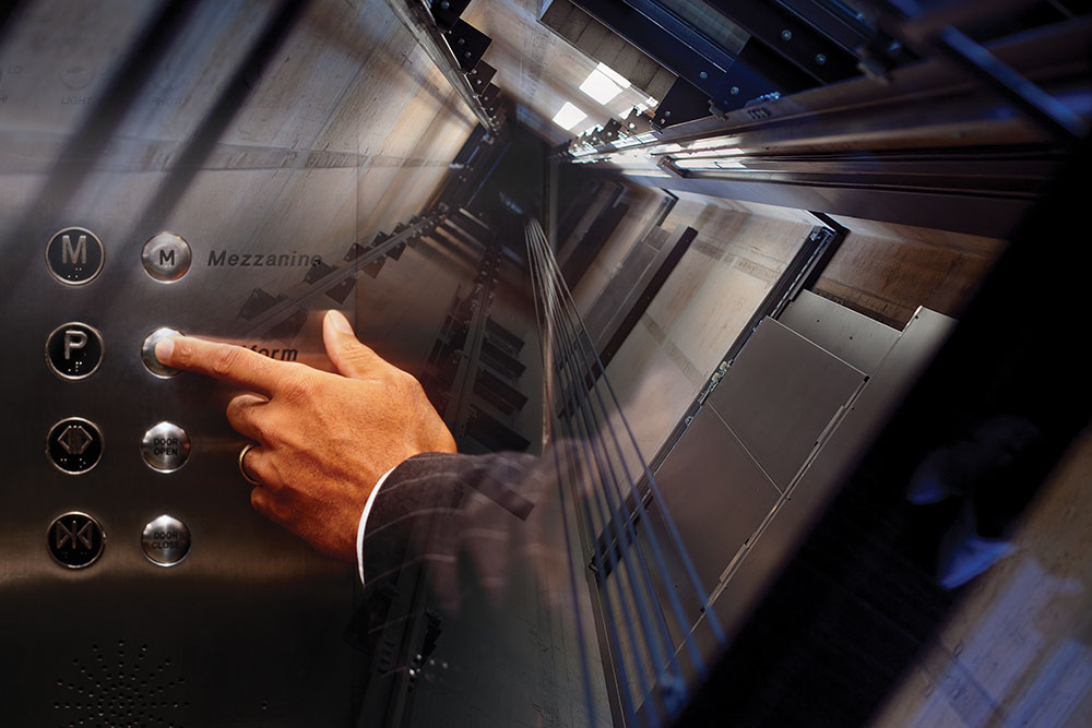
3. Arriving firefighters may initiate Phase II Emergency In-car Operation by using a key and pressing buttons inside the elevator car to close and open doors and to move the car between floors. Photo 1 shows a typical lobby elevator control panel with the key switch to select firefighter operation. Photo 2 shows a typical elevator car control panel, with the firefighter key switch and indicator lights in the red panel in the center and operating instructions in red directly above. In this way, firefighters can quickly move equipment to upper floors nearer the location of the fire and evacuate persons who are unable to self-evacuate using stairways.
4. If smoke is present at the top of the elevator hoistway or in the machine room, the smoke detector will activate a circuit in the elevator controller. This will cause the red firefighter helmet indicator light on the control panel (see photos) to begin to flash, indicating that smoke and fire are near the elevator machine or in the hoistway and that a power shunt trip is possible. The instructions on the panel in Photo 2 state, “WHEN [fire helmet] FLASHES, EXIT ELEVATOR.” Firefighters at this time have the choice of manually opening the elevator doors at the nearest floor and exiting the elevator or attempting to return the elevator car to the primary recall floor with the risk of becoming trapped in the elevator between floors when the power shunt trip breaker operates.
5. When significant heat is present at the top of the elevator hoistway or in the machine room, the heat detector near a sprinkler head will sense that sprinkler discharge is imminent and will cause the main elevator power to shunt trip without delay, without any action by the elevator controller. This power shunt trip breaker can only be reset manually in the elevator machine room. Disconnection of the elevator main power does not affect lights or communications with the elevator car, which are on separate circuits.
However, there are two (rare) scenarios in which firefighters or other building occupants could become trapped by a power shunt trip:
- A very slow elevator, or one with a great distance to travel, with a fast-moving fire in or near the elevator machine room. In this instance, the elevator does not have time to complete Phase I recall before the power shunt trip.
- A large-scale incident in a multistory residential building occupied by many persons who are not capable of self-evacuating by way of stairs, which could result in firefighters using the elevator on Phase II operation to the last possible moment to remove as many occupants as possible.
The author acknowledges the valued assistance with the research for this article by Brian Rausch PE, at the Wisconsin Elevator Safety Program of the Wisconsin Department of Commerce.

- Download this article as a PDF!
- More Construction Concerns
- More Building Construction
- More Fire Prevention and Protection
Subjects: Building construction for firefighters
Related Posts

Latest Fire Engineering News

Please check your spam folder and any email filters, in the event that the email gets blocked.

Stay informed about daily FireEngineering news, podcasts, training videos, webcasts, commentary, and exclusive articles about FireEngineering by signing up.
Unauthorized Request
Unauthorized activity detected.
Electrically Safe Work Practices — NFPA 70E Basics

Workforce Development and its Role in Electrical Safety

EFCOG Best Practice #240 — Electrical Utility Risk Assessment
Compliance with the 2017 NEC for Elevator Controllers
Traditionally, the electrical system design engineer has given little attention to the elevator controller. In fact, an entire elevator system for a project is most often designed and specified by the architect who has little understanding of the electrical distribution system. Because of this, there is often a communications gap between the electrical system designer, whose design typically stops at the required elevator disconnecting means, and the architect who designs the elevator system. To address this issue, Code Making Panel (CMP) 12 of the National Electrical Code ® acted on several proposed changes to Article 620 during the revision cycle for the 2017 NEC that deal with the proper installation of elevator controllers.

The proposals resulted in adding new requirements in the 2017 NEC for:
- Marking the elevator controller short-circuit current rating (SCCR) by the elevator controller manufacturer.
- Reinforcing NEC 3 (B) and NEC 110.10 to require the elevator controller marked SCCR to be equal to or greater than the calculated and marked available short-circuit (fault) current at the elevator controller.
- Marking the available short-circuit (fault) current on the controller by the equipment installer.
This article will also discuss other Code requirements that include selective coordination for elevators that are supplied by emergency, legally required standby or critical operation power systems or multiple elevators supplied from a single feeder, and shunt tripping of elevators where the elevator equipment room and/or shaft has a fire suppression sprinkler system. Finally, typical installations and compliance with all these requirements will be discussed.
Equipment SCCR and short-circuit current marking requirements
The reason the NEC CMP 12 added these requirements, as shown in the panel statements, directly relates to the concern that elevator controllers can be installed in locations where the available fault current can be high and the inspector may not be able to clearly determine the SCCR of the elevator controller unless it is marked on the equipment. The panel further clarified that the marked SCCR value must be adequate for the available fault current to ensure a safe installation. In order to aid enforcement, the panel additionally required marking the available fault current at the elevator controller. Below is a summary of these new 2017 NEC sections:
- 620.16(A) Manufacturers must mark their elevator control panels with an equipment short-circuit current rating (SCCR). The SCCR can be based on an assembly product standard listing and labeling, or an approved analysis method, such as UL 508A, Supplement SB.
- 620.16(B) If the elevator control panel SCCR is not equal to or greater than the available fault current, the elevator control panel must not be installed.
- 620.51(D)(2) An elevator control panel must now be field marked with the maximum available fault current along with the date the calculation was made. Further, if there is a change to the available fault current, then this field marking must be revised.
Complying with these new requirements
In order to comply with these requirements a chain of events must occur.
- The electrical system designer calculates the maximum available fault current at the elevator controller.
- The electrical system designer needs to communicate this information to the person responsible for specifying the elevator controller, which is most often the architect.
- The party responsible for procuring the elevator control panel must state the minimum acceptable SCCR or the maximum available fault current where the controller will be installed.
- The elevator controller manufacturer must determine the required elevator controller SCCR as stated in the elevator controller specification and provide an elevator controller SCCR that is equal to or greater than the available fault current that’s indicated in the design documents where there are multiple elevator controllers at different locations.

With these new NEC requirements, there is now the potential that an elevator controller SCCR may be required that’s higher than what elevator manufacturers have historically furnished. As such, elevator controller manufacturers should make the effort to rethink their designs to avoid costly system design changes. For instance, a typical elevator controller may traditionally have SCCR ratings from 5 to 10 kA. However, it is likely that for many elevator controllers, this may not be high enough for the available fault current where they will eventually be installed.
Some elevator controller manufacturers believe this is an issue for the electrical system designer and installer to address and remedy by adding impedance to the system for lowering the available fault current. This, however, can result in a dramatic increase in cost, space availability (lack thereof), and reduced efficiency. For instance, one method to reduce the available fault current is to add an isolation transformer ahead of the elevator controller.
Many new buildings are incorporating an elevator design that does not include an equipment room (sometimes called machine room-less elevators). All equipment in a machine room-less design is installed within the elevator shaft or exterior compartment near the elevator shaft, including the elevator controller and the elevator disconnecting means. In these installations, it is best to design the elevator controller so the elevator controller SCCR is adequate for the available fault current. This is something that can be easily accomplished if the elevator controller manufacturer uses components in combination with overcurrent protective devices that are tested and listed with high combination SCCRs. In many cases, the overcurrent protective devices that are suitable for this level of protection are current-limiting fuses rather than a traditional circuit breaker. In this case, it may be best if the elevator controller manufacturer does not include the elevator disconnecting means (often offered as a circuit breaker) but instead have the installer provide a separate fused disconnect to comply with NEC 620.51(A) and also achieve a high SCCR for the elevator controller when fuses are provided as specified by the elevator controller and marked on the elevator controller nameplate.
Selective Coordination
If elevators are supplied by the emergency, legally required standby or critical operation power systems, then selective coordination is required per the 2017 NEC in 700.32, 701.27 or 708.54. Selective coordination is also required for multiple elevators per NEC 620.62. Another important electrical system design consideration for supplying power to multiple elevators is NEC 620.62. NEC 620.62 requires the elevator disconnecting means (fused switch or circuit breaker) to selectively coordinate with all supply-side overcurrent devices. Selective coordination is defined by the NEC as: “Localization of an overcurrent condition to restrict outages to the circuit or equipment affected, accomplished by the selection and installation of overcurrent protective devices and their ratings or settings for the full range of available overcurrents, from overload to the maximum available fault current, and for the full range of overcurrent protective device opening times associated with those overcurrents.”
In order to comply, the electrical system designer must determine the maximum available fault current at the elevator disconnecting means and assure the elevator disconnecting means overcurrent protective device will clear any overcurrent condition, up to the maximum available fault current, before any upstream overcurrent devices will operate. Notice the definition mentions the full range of operating times. This is important as the tradition of using only time-current curves for the analysis of overcurrent device operation is usually not sufficient since the time-current curves traditionally stop at 0.01 second (not time “zero”).

For current-limiting fuses, the information to achieve selective coordination has been available for many years in fuse amp ratio tabular form. These selective coordination tables for current-limiting fuses show the minimum amp ratio required between a pair of fuses of a given type(s) to achieve selective coordination.
For circuit breakers, time-current curves must be consulted as well as the circuit breaker manufacturer’s selective coordination tables. These circuit breaker selective coordination tables can be used to identify the maximum fault current that a pair of circuit breakers can selectively coordinate. It is important to note, that these selective coordination tables can indicate a lack of selective coordination at a given fault current for circuit breakers that do not show overlap on the time-current curves of the circuit breakers. For some manufacturers, such as Eaton, testing has been completed to determine the selective coordination ability of current-limiting Bussmann TM series fuses with upstream Eaton circuit breakers.
Shunt Tripping
Where the elevator shaft and/or equipment room has a sprinkler fire suppression system installed, the elevator Code requires main line power to the elevator be removed prior to the application of water. This is typically accomplished via a shunt trip device.
There are options available to achieve this depending upon the customer’s needs. The simplest option is to use a shunt trip circuit breaker in either the feeder supplying the elevator or the elevator disconnect. For elevators with battery lowering systems, an additional contact must be supplied and wired to disable the battery lowering system when the elevator disconnect is manually operated for maintenance. NFPA 72 requires the control circuit between the Fire Alarm System and the shunt trip be monitored for integrity. In addition, the shunt-trip voltage must also be monitored by the Fire Alarm System. Loss of voltage to the control circuit for the disconnecting means shall cause a supervisory signal to be indicated at the control unit and required remote annunciation. In some cases, it may require a means to test the shunt trip operation or have one contact operate the shunt trip of more than one elevator. Per the 2017 NEC , if the elevator is designated as an emergency system load, the disconnect must be protected by a surge protective device (SPD). All of these options and special wiring can be challenging depending upon the location of the shunt trip circuit breaker as well as who has responsibility for providing these additional options. Because of this, several manufacturers offer an all-in-one shunt trip elevator disconnect switch that includes all the prewired accessories needed to comply with the various Code sections.
Typical Elevator Installations
The architect has a choice of either traction or hydraulic elevators. Traction elevators are typically faster and more energy efficient than hydraulic elevators, and are often used for high-rise buildings. Hydraulic elevators are typically more cost effective and used for buildings up to 5-6 stories. Traction elevators are typically installed in a “bank of elevators” where fused switches, or circuit breakers in a panelboard are located in the machine room serving the bank of elevators. Each fused switch or circuit breaker in the panelboard is used as an elevator disconnect. Hydraulic elevator installations are typically supplied from the main switchboard and have an elevator fused switch or circuit breaker in the machine room that serves as the elevator disconnect.

As mentioned, traditional installations of a traction or hydraulic elevator include a separate machine room. The vast majority of equipment serving the elevator is located within this room (i.e., elevator controller). Also located in this room might be, but not limited to: exhaust fan, cooling unit (depending on local requirements and/or requirements set forth by the individual elevator supplier), lighting, voice and/or data drop serving the elevator cab emergency phone, elevator controller primary fused disconnect, elevator feeder shunt-trip circuit (i.e., shunt-trip circuit breaker), elevator cab lighting fused switch, and convenience receptacle(s).
Machine room-less elevator installations incorporate the elevator controller and often the primary disconnecting means in a convenient package that is located within the elevator shaft. However, space is frequently limited within the shaft and as such many ancillary components (shunt trip circuit breakers, fused disconnects) may need to be located outside of the elevator shaft. It is important for design engineers to communicate this with the architect and owner during the design phase, as it will impact space needs elsewhere in the facility to accommodate electrical equipment.
A traditional elevator installation (which includes a machine room) requires access inside the elevator shaft. Convenience receptacles and lighting for maintenance purposes are required at the base of the pit and, in some instances (elevator manufacturer dependent), at the top of the elevator shaft. It is important for the design engineer to coordinate with the architect to determine the elevator manufacturer basis of design to determine if and when additional power and lighting is required.

It is of great importance for the design engineer to communicate with their local authority having jurisdiction (AHJ) to determine fire alarm requirements for the respective elevator installation. While machine room-less designs have been commercially available for many years, their use may still be unknown to some AHJs. Design practices that are acceptable in some jurisdictions may not be in others. As always, the best advice in all instances…do your homework, communicate often, and document decisions made. Years may lapse between the design and installation stages of a project. Good documentation is of key importance to recalling what decisions were made and why.

With the new elevator controller requirements, more attention will be focused on the elevator system. First, it is now clear that elevator controllers must be marked by the manufacturer with their SCCR. The design engineer must identify the available fault current at the elevator controller to the installer so an elevator controller with adequate SCCR can be provided. If this is not done and the available fault current exceeds the elevator controller SCCR, other solutions to reduce fault current must be reviewed or equipment changes and field evaluations may be needed. In addition, requirements for selective coordination and shunt tripping should be complied with as needed for the installation.
What are the Safety Hazards of Inadequate SCC
The hazards are external to the equipment enclosure since equipment SCCR testing and evaluation criteria for product standards are most often performed with the enclosure doors closed and latched, and the fault occurring external to the enclosure. Installing electrical equipment where its SCCR is less than the available short-circuit current creates serious safety hazards. These may include:
- Shock: The enclosure becomes energized from conductors pulling out of their terminations or device destruction occurring within the enclosure.
- Fire: The explosive power of the internal devices failing causes the closed and latched door to become ajar and spew flame and molten metal to the exterior. This is a fire hazard to both the facility and personnel.
- Projectile (shrapnel): The enclosure door may blow open or off with fire and failing device debris (shrapnel) shooting out. In laboratory tests, equipment SCCR failures have resulted in enclosure doors explosively blowing off and flying up to 100 feet away. Additionally, the shrapnel, from the rapid failure of internal devices, can be ejected at speeds up to 700 miles per hour.
The author would like to recognize Jonathan Kennedy for his assistance in creating this article.
Air-Conditioning Equipment Installations

Basic three-phase power measurements explained

Safety in Marinas

Find Us on Socials
Raceway connections.
As an installer and an inspector, one common issue I've seeen is incompatible connections associated with raceways connections and fittings.

Safety After the Storm — Operating Portable Generators
Electricity is often one of the initial services to fail during a storm. Many people use portable generators until power is restored.

22 Ways to Make Members Feel Valued
Here are 23 ways that both chapters and the national office can meet today’s major challenge of making members feel valued
- Company News
Consulting Services
- Fire Protection, Life Safety, and Accessibility Code Consulting
- Healthcare Specialty Consulting
- NFPA 241, Construction Fire Safety, Permitting and Turnover Consulting
- Laboratory / Industrial / Hazardous Chemical Compliance Consulting
- Battery & Energy Storage System Fire Safety
Inspection, Testing & Commissioning
- Fire Door Testing and Inspections
- Firestop Special Inspections
- Life Safety System Re-Commissioning & Retro-Commissioning
- NFPA 3, Fire Protection System Commissioning and NFPA 4 Integrated Fire Protection and Life Safety System Testing
- Smoke Control Special Inspections
System Design
- Fire Alarm System Design
- Performance-Based Design
- Smoke Control System Design
- Fire Protection System Design
- Third Party Reviews
Back to Insights
Fire Alarm Interface with Elevator Recall
December 31, 2019 by Chad Farrell Jr., P.E.
Elevator recall for firefighter operations is a required function in all automatic elevators per 524 CMR, the Massachusetts State Elevator Code, which is an amended version of ASME A17.1 – 2013 Edition. Elevator recall is comprised of two distinct phases, each with their own controls, actions, and requirements.
Phase I Elevator Recall
Phase I elevator recall is an automatic sequence initiated by the fire alarm system to relocate an elevator cab to the designated recall floor. Activation of an automatic fire alarm initiating device located directly adjacent to an elevator door, an elevator hoistway, or within rooms or spaces containing elevator machinery and/or controls will result in associated automatic elevators initiating Phase I recall.
- Phase I recall will bring all elevators to the primary floor, with or without passengers.
- In the event that smoke is detected immediately adjacent to the elevator doors on the primary floor, Phase I recall will take the elevator to the alternative floor.
- The Fireman’s hat will illuminate steady when the elevator car is placed in Phase I recall. The Fireman’s hat will extinguish when the associated elevator car is put back into normal operation. The fireman’s hat will illuminate intermittently when the fire is in the hoistway or in the equipment/control room.
- Activation of the Fire Service Switch in the lobby will return the car to the primary floor.
Phase II Elevator Recall
Phase II elevator recall describes the fire department’s manual operation of elevators.
Fire Alarm Requirements
Every elevator (or group of elevators in the same hoistway) will need the following fire alarm devices:
- Smoke/heat detector in each elevator lobby on each floor;
- Smoke/heat detector in the elevator equipment room;
- Heat detector in hoistway, if permitted, if hoistway is sprinklered (Note: Sprinklers are not permitted in hoistways in MA)
- Relay for Primary Recall;
- Relay for Secondary Recall;
- Relay to illuminate Fireman’s Hat;
- Relay for Shunt Trip, if hoistway is sprinklered (Note: Shunt trip is not permitted in hoistways in MA)
- Monitor or zone for Shunt Trip Power Fail, if hoistway is sprinklered
*Please note that hoistway ventilation is no longer required under the newest edition of 524 CMR. Please find our other insight on elevators here for more information on this topic.
Application of any information provided, for any use, is at the reader’s risk and without liability to Code Red Consultants. Code Red Consultants does not warrant the accuracy of any information contained in this blog as applicable codes and standards change over time. The application, enforcement and interpretation of codes and standards may vary between Authorities Having Jurisdiction and for this reason, registered design professionals should be consulted to determine the appropriate application of codes and standards to a specific scope of work.

Related Posts
Elevator Hoistways Protection Requirements
Construction Hoist Requirements
Elevators | FSAE 10th Ed. MA Code Changes
- Oct 14, 2021
NFPA 72 Compliance: Fire Detection in Elevator Pits
Updated: Dec 8, 2021
Most states base their elevator regulations on ASME A17.1, Safety Code for Elevators and Escalators. In many cases, a sprinkler is required in the bottom of an elevator pit. When a sprinkler is installed, NFPA 72, Fire Alarm Code , and ASME A17.1 require elevator hoistway pits to be protected via fire detection devices.

Regulations:
Elevator hoistway pit detection poses a unique challenge for several reasons. The elevator pit is considered a harsh environment because of the potential for dust, dirt, and humidity. Over time, standard spot-type smoke detectors are prone to false alarms. The elevator pit is a location that is extremely difficult for functional testing of devices as required by NFPA 72. In some states, such as Massachusetts, sprinklers are not permitted in elevator shafts. When sprinklers are not installed in elevator shafts, NFPA 72 prohibits the installation of smoke detectors.
In sprinklered elevator shafts, heat detectors are required to be installed within twenty-four (24) inches of each sprinkler in the pit. The heat detector needs to have both a lower temperature rating and a higher sensitivity than the sprinkler. The design goal is to ensure that power is interrupted to the elevator prior to sprinkler discharge.
The smoke detector in an elevator pit plays an important role in elevator passenger safety. It is intended to successfully recall the elevator prior to elevator shutdown. Proper location and selection of initiating devices are key to minimizing the likelihood of passenger entrapment between floors. To achieve this, it is important to detect a fire in the elevator pit as soon as possible. A smoke detector detects the early signs of a fire before it generates significant heat.
While not currently in force in most jurisdictions, NFPA 72 , 2019 edition introduces an additional requirement that initiating devices installed in the elevator hoistway must be accessible for service, testing, and maintenance from outside the elevator hoistway.
Design Solutions
An ideal detection solution for an elevator pit is one that is compliant, effective, easily maintained, and economical.

For heat detection, a linear type detection wire can be used within the elevator pit to detect a fire. Linear heat detectors are functionally tested by shorting the end-of-line resistor. To ensure compliance with NFPA 72 and ease of testing, the junction box containing the end-of-line resistor should be located outside the elevator pit, preferably in the elevator machine room.
While the approach for heat detection is straightforward, heat detection is a bit more challenging. Air sampling smoke detection is a method of smoke detection where the physical detector is located remote from the protected area and a fan (aspirator) actively samples air from the protected area via a network of CPVC piping. There are full function air sampling detectors available that could certainly provide effective elevator pit smoke detection; however, this approach is typically cost-prohibitive. There are also air aspirating spot-type smoke detectors available that are listed for harsher environments such as an elevator pit. These spot-type air aspirating detectors can provide a cost-effective means for elevator pit smoke detection.
A key design consideration is including routing a test port back into a space containing the detector so that testing can occur without entering the shaft. It is also important to ensure a return pipe is routed back to the elevator pit so that after being sampled, air can be returned to the pit. In pits where high humidity may be present, providing a condensate drain leg within the sampling network should be considered.
F&T has successfully leveraged linear heat detection and spot-type air aspirating detection to provide owners with thoughtful, practical fire alarm solutions for elevator pits. Contact us today to learn more about how we can help you.

Written by:
Andrew Cicariello
Fire Protection Project Engineer
Contact me>
- MEP Engineering
Recent Posts
Using Window Sprinklers for Passive Fire Protection
What is an NFPA 241 Plan and Why Do I Need One?
Life Safety Code Issues to Consider when Converting Spaces for ICU and Overflow COVID-19 Patients
Comentários
The #1 website for NICET Practice Tests, NICET study guides, Fire Alarm Code Knowledge, and General Fire Alarm Topics. We have up to date information on the newest fire alarm trends such as fire service access elevators, mass notification, voice intelligibility, occupant evacuation elevators and two-way communication for Areas of Refuge. Topics also include fire alarm system programming and technical tips. Learn how to build the best ground fault meter with step by step instructions.
- NICET Exam Practice Test
- Bluebeam for Fire Alarm Design
- Occupancy FA Requirements
- 520 HZ Low Frequency Audible Tone
- Industry Links
- Conduit Bending
Saturday, May 18, 2013

Elevator Recall Programming for Fire Alarm
Easy way to breakdown elevator recall and shunt trip programming, elevator recall and shunt trip programming zones.

6 comments:
this is incorrect!! f/f hat should not be on same zone as shunt trip No hat would flash if power to car is off?
You were absolutly correct and I apologize for the mistake. I have made the adjustment to show the heats as shunt trip and the hoistway and equipment room smokes activating the F/F hat light. Thank you and good looking out!
thanks for the info, very useful.
This comment has been removed by the author.
The programming world, is very vast, and you have to do a lot of research, in order for you to be able to grasp, any programming language in its entirety. best R programming IDE
So if programming an AFP-200 you would have to program modules for primary,Alt and hat then also create zones for those modules then add those zones to the specific smokes?
IMAGES
VIDEO
COMMENTS
The purpose behind this allowance is to increase the potential for elevators to complete their travel to the recall level. Make note that the requirements of A17.1/B44 Safety Code for Elevators and Escalators would still apply. If your fire alarm system utilizes waterflow or pressure switches to activate the elevator shunt trip, any time delay ...
Elevator code; adopted by reference. 2.27.3.2.1 - In Jurisdiction not enforcing the NBCC, fire alarm initiating devices used to initiate Phase 1 Emergency Recall Operation shall be installed in conformance with the requirements of NFPA 72, and shall be located. At each floor served by the elevator; in the associated elevator machine room; and.
3005.5 Shunt trip. Where elevator hoistways, ... The fire door assembly shall comply with the smoke and draft control assembly requirements of Section 716.2.2.1.1 and be tested in accordance with UL 1784 without an artificial bottom seal. ... Activation of any fire alarm initiating device in any elevator lobby, elevator machine room, machine ...
In the upcoming week I plan to incorporate ASME A17.1 and it's impact on the fire alarm side of accounting for elevators, hence the big [DRAFT] watermark on this PDF. Click on the image below to get a PDF copy of the Fire Alarm Elevator Cheatsheet: If you know anyone that could benefit from this content, please consider forwarding them a link.
The elevator power shunt trip does not operate without warning. The complete sequence of operation and warnings begins with smoke detector that activates the Phase I elevator recall for ...
Elevator Shunt Trip - Fire Alarm Requirements. Here are the requirements for heat detector placement, monitoring of power and wiring diagram from 1999 NFPA 72: 3-9.4.1* Where heat detectors are used to shut down elevator power prior to sprinkler operation, the detector shall have both a lower temperature rating and a higher sensitivity as ...
Fire Alarm System and the shunt trip be monitored for integrity. In addition, the shunt-trip voltage must also be monitored by the Fire Alarm System. Loss of voltage to the control circuit for the disconnecting means shall cause a supervisory signal to be indicated at the control unit and required remote annuncia-tion.
International Fire Code, NFPA 72, and ASME A17.1; where initiating devices should be placed involving elevator equipment and proper signals generated at the fire alarm control panel. There is a specific focus on sequence of operations, cab recall, power shunt-trip, firefighter communication, and fire sprinkler interfacing. Presentation by:
NFPA 72 requires the control circuit between the Fire Alarm System and the shunt trip be monitored for integrity. In addition, the shunt-trip voltage must also be monitored by the Fire Alarm System. ... With the new elevator controller requirements, more attention will be focused on the elevator system. First, it is now clear that elevator ...
Fire hat 4. Shunt trip 5. AC power monitoring (only state that requires it) to my knowledge numbers 1,2,3,n 4 work NO number 5 works NC If memory serves ... Fire Alarm requirements for elevator fire service: NFPA 13, NFPA 70, NFPA 72, ANSI / ASME A17.1 A17.3
Fire Alarm Requirements. Every elevator (or group of elevators in the same hoistway) will need the following fire alarm devices: Smoke/heat detector in each elevator lobby on each floor; ... Relay for Shunt Trip, if hoistway is sprinklered (Note: Shunt trip is not permitted in hoistways in MA)
the power is supplied from the fire alarm system. In addition to turning off power, the model codes require other functions that are satisfied by the Eaton elevator disconnect (Figure 1, Note 3). One of these requirements is that the shunt trip control circuit requires monitoring. The 2002 NFPA 72 (fire alarm code) in Section 6.15.4.4 requires:
In this video I show the most common way I've seen elevator shunt trip setup and wired. I explain the concept behind elevator shunt trip and then explain how...
When a sprinkler is installed, NFPA 72, Fire Alarm Code, and ASME A17.1 require elevator hoistway pits to be protected via fire detection devices. Regulations: Elevator hoistway pit detection poses a unique challenge for several reasons. The elevator pit is considered a harsh environment because of the potential for dust, dirt, and humidity.
If you really want to get into the weeds, the WAC references the elevator code (Specifically, ASME A17.1, 8.6.4.19.6). It states: At least once each year, the fire alarm initiating devices associated with elevator recall and shunt trip initiating devices shall be tested to ensure they are still properly interfaced with the elevator control.
Building codes, elevator codes and fire alarm codes and standards all play a part to require recall and how the recall function should operate. The ASME A17.1 Code provides requirements for operational sequences for Phase 1-Emergency Recall Operation and Power Shutdown-"Shunt Trip" Operation.
9 - Designated elevator recall relay. 10 - Alternate elevator recall relay. 11 - Shunt trip relay. 12 - Elevator battery back-up relay. 13 - Elevator fireman's hat light relay. Now that we have all of our fire alarm devices associated with the elevator recall functions written down, it's time to place them in groups or zones.