Form Traveller System Bridge Construction: Out-spanning Traditional Methods
The use of form traveller systems offers significant cost savings for bridge construction projects throughout the world. We've partnered with Miguel Barreto from ConstruGomes of Portugal to highlight the key aspects of form traveller systems: how they offer cost advantages over traditional construction systems, in what situations they can best be utilized, and how they function.


Form Traveller Bridge Construction
Form traveller specifics.
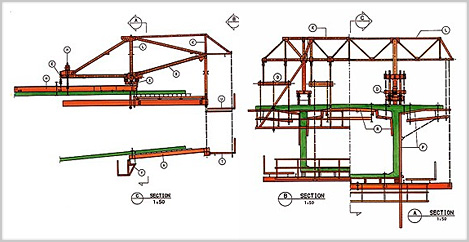
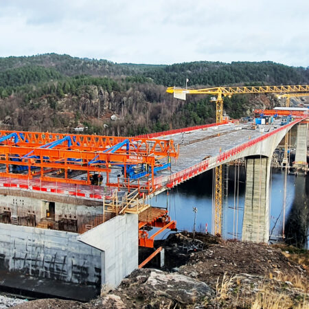
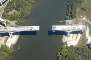
Form travellers can be employed during cantilevered concrete girder construction when a bridge pier can be used as a starting point. Opposite directions of span construction are facilitated by using the top of a pier as the initial anchor point for two separate form travellers (each pair of form travellers operates as a unit). Cantilevered construction is allowed by moving each pair of form travellers farther away from a pier in tandem. The weight is therefore always balanced, and the static forces on the pier maintain equilibrium. The incremental movement of each pair of form travellers is the critical path to project completion.

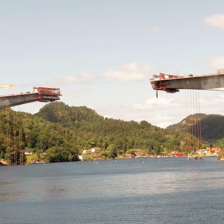
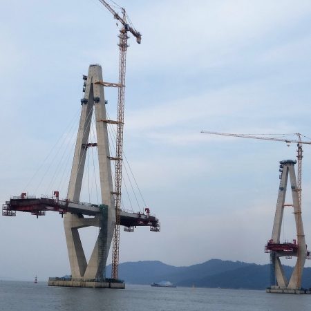
Work progress is limited to span increments of approximately 5 m (approx. 16') or 400 tons per week on each side of a pier. However, the key advantage of form travellers is their ability to span great distances in remote locations. If the contractor can access the piers, the bridge can generally be built with form travellers, including angled bridge decks with varying turn radii. Form travellers are preferred for building spans over deep valleys, waterways, and roads where access from the ground is a challenge and the number of piers is limited (especially for the central span).
- Form Traveller Delivery: Form traveller equipment can be trucked to the job site in multiple shipments or barged to the site if a bridge is being constructed over a navigable waterway.
- Form Traveller Operation and Training: Form travellers are powered by a hydraulic system, requiring the crews that operate them to receive specific training. The structural framework of the form traveller moves forward on rails anchored to the previously constructed span segments. The individual steel structural members of each form traveller are connected with pins to facilitate mobilization/demobilization.
- Form Traveller Installation: Form traveller equipment is assembled on the ground, and segments are then lifted by crane to their starting points on a specific bridge pier. Demobilization follows the same process in reverse. Sections are placed on the ground by crane and further disassembled into shippable parts.

Form Travellers vs. Traditional Construction
The main advantage of form travellers over other construction methods is that they allow for longer and wider spans to be built in challenging site conditions. Form travellers are better suited for bridge designs involving fewer piers because they can span much greater distances than other methods. This chart generically summarizes the maximum spans, widths, and timelines allowed by various concrete bridge construction techniques.
Moving Scaffolding Systems (MSS)
Moving scaffolding systems (MSS) cannot take full advantage of cantilevered construction techniques as compared to form travellers. Customized (expensive) MSS equipment is required for bridge decks greater than 20 m (approx. 65'). Moving scaffolding systems can be more cost-effective for long bridges with equal repeated spans (or multiple spans) because it is generally a quicker method: 30–60 m (approx. 98–196') span every week, or 60–90 m (approx. 196–295') span every two weeks. For bridge decks with a substantial turn radius, the MSS become less easy to operate. The MSS structure has to extend outward and move around constructed bridge piers as shown in this video .

Incremental Launching
Incremental launching is preferred for long straight bridge spans or those with a large and constant turn radius. This method becomes less feasible when the design requires an angled bridge deck relative to the horizon or a flat deck with a varying turn radius. The placement of each span increment is limited by the size of the hydraulic system pushing each span segment into place. Initial installation costs of the launching equipment (cables, hydraulics, rollers, etc.) is high, generally becoming more cost-effective as total bridge lengths approach 400 m (approx. 1,312'). It is usually good for small wide bridge decks that can be built in consistent segments, such as railroad bridges. It is also a good option in places where the bridge is high because the contractor doesn't need to use cranes or transports along the bridge to place deck segments. Concrete and steel materials are staged at a consistent location, so the system works similarly to a production factory.

Pre-Cast Materials
Pre-cast construction is often not suitable for larger spans. The length of the pre-cast concrete members is limited by factory equipment, the behavior of formed concrete, and shipping considerations. The use of pre-cast members is not feasible in some remote areas due to poor access roads. Transporting and elevating pre-cast members with cranes can be particularly challenging for bridge projects with poor access, rivers, or low support conditions. The higher a project’s bridge piers, the higher the cost of crane operations (i.e., larger crane equipment is required).

Heavy Propping and Traditional Scaffold Formwork
When the bridge spans are located at significant heights above grade, traditional formwork becomes no longer feasible since it requires bracing to ground. It becomes more labor-intensive and tedious as span lengths and pier heights increase. ConstruGomes has used heavy propped formwork up to only 40 m (approx. 131') of bridge span and height. These systems are normally limited to a height of 40 m because of material limitations and safety considerations. The spans can be large because they can have multiple support towers on the ground. The limit of 40 m of span is between a set of propping towers only.

Self-Climbing Formwork
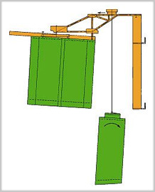
Self-climbing formwork operates similarly to form travellers but builds piers vertically in increments as opposed to bridge decks laterally. Self-climbing formwork is installed at grade and can be used to construct the entire height of a new cast-in-place concrete pier. Lifts of up to 5 m (approx. 15') every 2–3 days can be achieved. Self-climbing formwork needs a constructed pier height of only 1 m (approx. 3') to begin operations.

Image Gallery
This image gallery below of ConstruGomes projects in the Marao Mountains and the Azores highlights their use of form travellers and self-climbing formwork in state-of-the-art bridge construction.

Like this article? Sign up for our monthly newsletter and get the latest updates!

Andrew Kimos
Andrew Kimos completed the civil engineering programs at the U.S. Coast Guard Academy (B.S. 1987) and the University of Illinois (M.S. 1992) and is a registered Professional Engineer in the state of Wisconsin. He served as a design engineer, construction project manager, facilities engineer, and executive leader in the Coast Guard for over 20 years. He worked as a regional airline pilot in the western U.S. before joining the Buildipedia.com team as Operations Channel Producer.
Latest from Andrew Kimos
- Case Study: Water Quality Retrofit and Retaining Wall Remediation
- Construction Documents Technology Proves Cost-Effective
- In-Situ Pipe Repairs Save Time and Money
- In Situ Pipe Repairs Save Time and Money
- U.S. Infrastructure: Drinking Water
At Home Topics
- Everyday DIY with Jeff Wilson
- 60 Simple Seconds
- Jeff Wilson Everyday DIY Blog
- Rehabitat with Rachael Ranney
- Design & Remodeling
- Landscaping
- HVAC | Electrical | Plumbing
- Walls | Windows | Doors
AEC Pros Topics
- Featured Architecture
- Design News
- Solar Decathlon
- Construction Materials & Methods
- From the Job Site
- Engineering News
- Public Infrastructure
- Facilities Ops & Maintenance
- Urban Planning
- CSI Project Solutions
Knowledgebase
- Division 02 Existing Conditions
- Division 03 Concrete
- Division 04 Masonry
- Division 05 Metals
- Division 06 Wood, Plastics, and Composites
- Division 07 Thermal and Moisture Protection
- Division 08 Openings
- Division 09 Finishes
- Division 10 Specialties
- Division 11 Equipment
- Division 12 Furnishings
- Division 13 Special Construction
- Division 14 Conveying Equipment
- Division 21 Fire Suppression
- Division 22 Plumbing
- Division 23 HVAC
- Division 26 Electrical
- Division 27 Communications
- Division 28 Electronics Safety and Security
- Division 31 Earthwork
- Division 32 Exterior Improvements
- Division 33 Utilities
- Find Us on Twitter
- Find Us on Facebook
- Find Us on YouTube
- Find Us on Pinterest
- Editorial Calendar
- Advertising
- Writers Guidelines
- Terms and Conditions
- Construction Calculator: Simplified Construction Cost Calculator
- Members Login
What Is Form Traveler In Construction?
- Building & Construction
A form traveller is a type of travelling formwork system used in bridge construction. It enables the repeated construction of structural elements and is typically used for free cantilever construction of post-tensioned box girder and cable-stayed concrete bridges.
Form travellers are supported by the part of the structure already built, and can be overhead or underslung
Form traveller is a system used for free cantilever construction of post-tensioned box girder and cable-stayed concrete bridges. It is lightweight, versatile, easy to assemble and operate, rolling forward on rails or rollers, and supports the weight of the construction elements including formwork, traveler, reinforcement and uncured concrete.
The form traveller system is designed to be highly stable and rigid so that it does not move significantly under the weight of the concrete as it is poured or during curing. It also has features such as being portable and cost effective.
The Standard form traveller is intended to be used for bridge construction and has a maximum segment length of 5 meters. The load capacities for concrete and formwork can range from 250 to 400 tonnes. The weight of the steel used in the form traveller depends on the specific cross-section of the bridge, typically ranging from 25 to 65 tonnes.
It is possible to modify the Standard form traveller to fit almost any cross-section and adjust it during use to accommodate changes in segment length, section height, web thickness, and deck width.
What Is Form Traveler Used For?
Form travellers are used for free cantilever construction of post-tensioned box girder and cable-stayed concrete bridges. They are lightweight, versatile, easy to assemble and operate, rolling forward on rails or rollers, and offer significant cost savings over traditional methods.
Form travellers are preferred for building spans over deep valleys, waterways, and roads where access from the ground is a challenge and the number of piers is limited.
The main advantage of form travellers over other construction methods is that they allow for longer and wider spans to be built with less material than traditional methods.
Form travellers come in two types: overhead form travelers which are suspended underneath the bridge structure already erected, and under-slung form travelers which are mounted on top of the structure already erected.
Is Form Traveler Used For Construction Of Superstructure?
Form travelers are commonly used for the construction of cantilever segmental bridges, as they provide a convenient and efficient means to build superstructures.
These form travelers give shape to the segment, support the weight of the newly cast concrete until it has gained enough strength to be post-tensioned to the previous cantilever segments, and transfer the segment weight to the already existing superstructure.
Form travelers can also be used in certain circumstances for other types of bridge structures (such as truss or arch bridges), depending on the specific design requirements.
Form Traveller Installation
Installation of form traveller involves assembling the equipment on the ground and lifting segments by crane to their starting points on a specific bridge pier.
Form travellers come in two main types: overhead and underslung, with both being designed for free cantilever construction of pre-stressed girder and cable–stayed concrete bridges.
Structural analysis is used to improve the performance and alignment of bridges, as well as ensure that the formwork does not move significantly under the weight of the concrete during pouring or curing.
Form Traveller Components
Form traveler components consist of a main frame, walking and anchoring device, bottom mould frame, side mould frame, inner mould frame, front lifting device and rear lifting device which are important for the smooth functioning of form travelers.
The main frame provides stability to the whole assembly while the walking and anchoring devices assist in its movement. The mould frames form an enclosure for supporting the form structure pieces and the lifting devices on both ends help in moving them between different levels.
Related Posts
What is an electroless plating.
What Is An Electroless Plating? Electroless plating, also known as chemical plating or autocatalytic plating, is a method of creating a metal coating on a variety of materials through the use of a chemical bath that reduces metal cations. This process differs from electroplating, in which an electric current is used to create the metal […]
What Is Exterior Insulated Finishing System?
What Is Exterior Insulated Finishing System? Exterior Insulated Finishing System (EIFS) is a non-load bearing building cladding system that provides exterior walls with an insulated, water-resistant, finished surface in an integrated composite material system. EIFS has been in use since the 1960s in North America, and was first used on masonry buildings. Since the 1990s, […]
What Is A Facing Tool In Metalwork?
What Is A Facing Tool In Metalwork? A facing tool is an important tool in metalwork that is mounted into a tool holder and placed onto the carriage of the lathe, allowing the user to cut away material from the outer surface of a rotating piece. Facing tools feed perpendicularly across a part’s rotational axis […]

Construction Technologies & Engineering, Inc.
Structural and construction engineering, antlers bridge – california.

For this project, we redesigned existing form travelers already owned by the supplier to fit the new bridge cross-section. We performed the required structural analysis and produced the modification drawings. We also calculated the form traveler reactions and the expected formwork deflections. These parameters are required for checking construction stresses and developing proper casting curves for the bridge superstructure. The immediate form deflections are combined with long-term creep and shrinkage deformations to determine the theoretical formwork elevations at the time of the segment pour. Form travelers, also referred to as bridge builders, are self-launching formwork systems that support themselves entirely off the previous segment for constructing the current segment. Once the concrete has reached the specified strength, the longitudinal tendons are stressed and the bridge builder is advanced by one segment length. The form traveler is launched on a set of rails, which also provide the reaction at the back to prevent the system from over-turning.


BRIDGEBUILDER FORMTRAVELLER
Travelling formwork system for free cantilever construction.
BRIDGEBUILDER Enhance The Economic Performance of Bridge Projects.
Reliable Bridge Construction Equipment for Free Cantilever Construction with NRS Innovation and Solutions.
“BRIDGEBUILDER” FORMTRAVELLER
The Overhead and Underlane NRS Formtraveller which is widely and well known as the Bridgebuilder, is the most reliable and extensively used FormTraveller system in the world for in-situ construction of free cantilever post tensioned box girder bridges as well as cable-stayed concrete bridges.
It has been adopted as the de facto design that is widely used among all suppliers in the industry.
To date NRS has supplied more than 1000 units of Bridgebuilder worldwide.
The “Bridgebuilder” formtraveller system was invented in 1970 and today it is acclaimed for enhancing the cost-effectiveness of bridge projects worldwide.
The Bridgebuilder has undergone vast improvements over the years and incorporated innovative solutions, making it a developed, practical and reliable system for contractors.
Today the Bridgebuilder is a versatile, lightweight, easy-to-assemble and operate.
The system is designed with the following cost savings solutions:
- Special “Fast-Split” installation method on hammerhead as short as 7m long.
- NRS Bridgebuilder with cross member for Hammerheads as short as 3m.
- Back launching to pier for ease of dismantling after use
- Use of Bridgebuilder for casting hammerhead
- Casting closure segment stitches.
STANDARD CONVERTIBLE BRIDGEBUILDER
The Standard Bridgebuilder is designed for a maximum segment length of 5 m and load capacities (concrete and formwork) varying from 100 tons to 400 tons. The steel weight depends on the cross-section of the bridge in question, but will normally vary from about 25 tons to 65 tons correspondingly. The Standard Bridgebuilder may be adapted to suit almost any cross-section, and is easily adjustable during operation to variations in segment length (up to 5 m), section height, web thickness, and deck width.
TAILORED BRIDGEBUILDERS
The Bridgebuilder may be tailor-made for segment lengths beyond 5 m and other extreme conditions. Alternatively it may be designed for shorter lengths where the maximum segment length is less than 5 m, and there is a requirement to reduce the weight of the Bridgebuilder for a particular application.
NRS Special Bridgebuilder for arch bridge construction has also been used successfully for the construction of the 323m arch bridge at the Hoover Dam Bypass project – the longest arch bridge in North America and the 4 th longest concrete arch bridge span in the world.
Modern bridges are becoming wider and longer but at the same time clients and contractors are seeking shorter construction time. In NRS, pursuing improved and innovative solutions to meet these requirements has always been one of NRS main goals.
NRS never fails in giving innovative designs even for conventional equipment like the Formtraveller
THE BRIDGEBUILDER FEATURES
- Lightweight
The use of rectangular hollow sections in the main structural components and recoverable high strength bars in all stays and ties reduces the total steel weight to a minimum.
- Versatile and Flexible Design
The Bridgebuilder may be adapted to almost any cross-section and is easily adjustable during operation to variations in segment length, box height, web thickness, deck width and road alignment (gradient, curvature, super-elevations).
- Small Deflections
The vertical deflection at the front of the Bridgebuilder is less than 25 mm at maximum load. Formwork beams are designed for a maximum deflection of 1/400 of their length.
- Easy Assembly and Operate
-One Bridgebuilder may be assembled in one week. Rolling forward on rails, the reset time is short.
-Lifting system to lift and install the whole Bottom slab for Overhead BB FT and the whole pre-assembled on ground Underlane BB FT.
– Rebar Carrier and trolley system
SPECIFIC DETAILS
Technical principle & working cycle.
A normal working cycle may be as follows:
- The Bridgebuilder, except for the internal formwork, is launched into position for a new segment
- The external formwork is levelled and fixed.
- Bottom slab and webs reinforced.
- The internal forwork is pulled forward.
- Concreting of bottom slab and webs. The top slab may be cast after a short intermission to allow setting of the concrete in the webs, or it may be cast the next day.
- After sufficient concrete curing, post-tensioning takes place.
- Form work is loosened, and the Bridgebuilder launched forward to the next segment. In most cases one cycle is carried out in one week. There are examples of 4-5 days cycle.
MAIN PRINCIPLE & COMPONENTS
Cross-Member For Installation On Small Pierheads
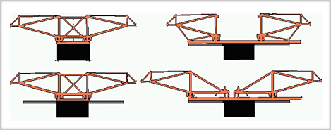
When the pier head is too small to allow normal assembly of the Bridgebuilder, our patented Cross-member solves the problem. It makes it possible to start free cantilevering from pier heads as small as 3 m. The procedure is illustrated through the above 4 phases.
Precast Segmental Bridgebuilder
The Precast Segmental Bridgebuilder is equipped with two hoists for lifting the precast segments as well as for adjusting the crossfall. A manipulator permits adjustment of the longitudinal fall and hydraulic cylinders launch the device forward.
The World's 10 Longest Free Cantilever Concrete Bridges
Some of the world’s most outstanding bridges have been built by use of the NRS Bridgebuilder Formtraveler. Refer to the table below.
OH-BB FT TRYSFJORD BRIDGE, NORWAY
UL BB FT YEONGGWANG – HAEJE BRIDGE, KOREA
OH BB FT Gabrovo, Bulgaria
Overhead Form Traveller
- Design, fabrication, delivery and technical assistance to the new equipment
What Is Overhead Form Traveller
The Form Traveller is a temporary support structure supporting the weigh of the bridge and viaduct deck segments cast in situ built by the cantilever method from the pier head to the center of the span.

Safe, Typical, Adjustable
- Adjustable to the variations of segment length, cross section height, web thickness, and deck width
- Easy to fit almost any deck cross section
MIDAS software calculation
- Reduced weight, saving prestressing in the deck construction phase
- Easy to transport

Save Cost to Be Reused
- Easy to assemble, launch-back and disassemble
- Reusable multiple times
Pre-test and Pre-load
- Reduced deformations
- Easy to adjust the height for the curves

Form Traveller Frame System
1. Main frame system
- Upper bracing
- Lower bracing
- Front bracing
- Rear bracing
- Vertical bracing
2. Main support structure system
- Bottom longitudinal beam
- Front support beam
- Rear support beam
3. Launching device and anchor system
- Front bogie
- Rear pull-down beam
- Launching device
4. Hoisting System
- Support beam hoist
5. Formwork system
- External formwork
- Internal formwork
- 0# Block formwork
6. Working platform system
- Upper working platform
- Lower working platform
- Front ladder
- Rear ladder
- Protective guard
Expert at This Area
Our service.
- Tender stage quotation preparation
- Rebuilt design regarding existing equipments delivered by us, for use in different conditions of the original
Send a Message
Your contact to ohc.
Address: 195, E. 4th Ring Rd Middle, Chaoyang District, Beijing, 100124, China
Phone: +86 13941265037
Thank you for your interest in OHC Formwork. To help us promptly meet your request, please Send a Message, Email, or Call Us, Follow Us.
Overhead Form Traveller/ Bridge Builder - BECT Ltd
- BECT Ltd - ABOUT US
- DESIGN & CONSULTANCY
- CONSTRUCTION ENGINEERING
- Construction Equipment
- Underslung Form Traveller
- Overhead Form Traveller
- Underslung System
- Overhead System
- Underslung LG
- Overhead LG
- Beam Launcher (BL)
- Segment Lifter (SL)
- Overhead FT Components
- Underslung FT Components
- Overhead FT Operation
- Special Arrangement System

form-traveler-bridge-construction
IMAGES
VIDEO
COMMENTS
The use of form traveller systems offers significant cost savings for bridge construction projects throughout the world. We've partnered with Miguel Barreto from ConstruGomes of Portugal to highlight the key aspects of form traveller systems: how they offer cost advantages over traditional construction systems, in what situations they can best be utilized, and how they function.
A form traveller is a type of travelling formwork system used in bridge construction. It enables the repeated construction of structural elements and is typically used for free cantilever construction of post-tensioned box girder and cable-stayed concrete bridges. Form travellers are supported by the part of the structure already built, and can ...
integrated ladders, complete with ladder-cages. the safety feature which self-locks the CFT while it is being advanced on sliding plates. With the newly developed cantilever forming traveler, the 20 ft. long deck segments of the Viaducto de Teror are being cast in a weekly cycle. The pier-heads on this technically challenging bridge project ...
As the segment is long and heavy in the cantilever casting construction of the arch bridge, 29-34 a new type of triangle truss form traveler (hereinafter referred to as the form traveler) is proposed. The form traveler mainly consists of the bearing system of the main truss, the stay cable, the C-type hook, and the walking track.
The form traveller system is acclaimed for enhancing the cost-effectiveness of bridge projects worldwide. The system is lightweight, versatile, easy to assem...
The underslung Form Traveller system can be adapted to different types of bridges, such as arch and cable stayed structures, leaving no obstructions to temporary or permanent cables. A standard underslung Form Traveller is designed for a segment length of 5 m. It can be tailor made for various segment lengths.
Form travelers, also referred to as bridge builders, are self-launching formwork systems that support themselves entirely off the previous segment for constructing the current segment. Once the concrete has reached the specified strength, the longitudinal tendons are stressed and the bridge builder is advanced by one segment length. The form ...
The Doka cantilever forming traveller provides certainty regarding planning and costs while ensuring an optimum construction workflow. The perfect design match between the CFT's shoring structure and the formwork, its high standard of safety and its optimised workplace-ergonomic design together ensure that work can progress swiftly ...
A form traveler used in bridge construction has a great influence on the safety of the performance and alignment of bridges. As a cantilever casting segment of a bridge becomes longer and heavier ...
Formwork traveller systems for fast and safe construction. Travelling formwork can be used for a large variety of different structures, from tunnels, bridges and reservoir walls, to sea walls and walls running adjacent to rail lines. Essentially, a travelling formwork system enables the repeated construction of structural elements and so is ideally suited to long stretches of repetitive ...
The Standard Bridgebuilder is designed for a maximum segment length of 5 m and load capacities (concrete and formwork) varying from 100 tons to 400 tons. The steel weight depends on the cross-section of the bridge in question, but will normally vary from about 25 tons to 65 tons correspondingly. The Standard Bridgebuilder may be adapted to suit ...
The document discusses Huada Heavy Industry's Form Traveller System, which is used for segmental bridge construction. The system can be designed as overhead or underslung and adapted to different bridge cross-sections. It allows efficient reuse on bridges with varying dimensions. Hydraulic and mechanical systems provide precision control during construction. Both overhead and underslung models ...
Design, fabrication, delivery and technical assistance to the new equipment. Rebuilt design regarding existing equipments delivered by us, for use in different conditions of the original. form traveller is a temporary support structure supporting the weigh of the bridge and viaduct deck segments cast in situ.
A form traveler used in bridge construction has a great influence on the safety of the performance and alignment of bridges. As a cantilever casting segment of a bridge becomes longer and heavier, the traditional form traveler may not ... system of the main truss, the stay cable, the C-type hook, and the walking track. The C-type hook is con-
Form Traveller is widely used in the world for the construction cast-in-situ of balanced cantilever bridges. The form traveller can be customized to meet clients' requirements and designed to comply with international codes. The equipment is self launching with back launching option for dismantling. Hercules Structural offers self launching ...
Form-Traveller whether Overhead or Underslung Model is usually used for cast-in-situ bridges constructed by a balanced cantilever method. The overhead model is more common and easier to use compared with the Underslung Model. The Underslung Model becomes superior when construction clearance over the formwork is required, such as cable-stayed and arch bridges, or construction requirements such ...
The Doka cantilever forming traveller provides certainty regarding planning and costs while ensuring an optimum construction workfl ow. The perfect design match between the CFT's shoring structure and the formwork, its high standard of safety and its optimised workplace-ergonomic design together ensure that work can progress swiftly and safely.
Form Traveler. Form traveller is the main equipment in balanced cantilever construction, according to the structure can be divided into truss type (including diamond, triangle, etc.), steel type and mixed type.
Construction Systems. Heavy Lifting, Lowering, & Sliding; Bridge Erection & Construction Systems; Products for Existing Construction. Structural Strengthening. CSS V-Wrap™ Systems; Strengthening with Post-Tensioning; Tstrata Enlargement Systems™ DUCON® Micro-Reinforced Concrete; Corrosion Control. ElectroTechCP™ Impressed Current ...
Specific Features of Standard Inspection of Bridge Structures in Moscow, Russia. Even though they are similar in structural form, design development, and construction methods, urban bridges differ substantially from highway bridges. However, a uniform technical surveillance system is in use for both bridge types.
Facts. 164 000 m² total area. 246 m tower height. 55 aboveground floors. 60 000 m² cold-formed glazing area. 1 floor in 6 days the speed of erection of the building frame. 1 350 underground parking capacity. 90° angle of reflection on the façade. 156° turn the building by around its axis.
buildings of Moscow City in the form of a system of 5-10-story frame blocks above the communication floor. So, in the «Burj Khalifa» building in the UAE, up to 20 floors are «suspended» to the communication unit. It is accepted that every 15-20 floors of a high-rise system, the building is divided by
Nevertheless, the date of the construction is still open, even though the discussion has started several years ago. Earlier, in 2014, Sergey Kuznetsov, the main architect of Moscow, said that the new bridge will allow stretching the pedestrian area, which is now interrupted by the traffic of the Yakimanskaya embankment.